Section 3 - Unpacking and Setup
Tooling Hub & Fixture
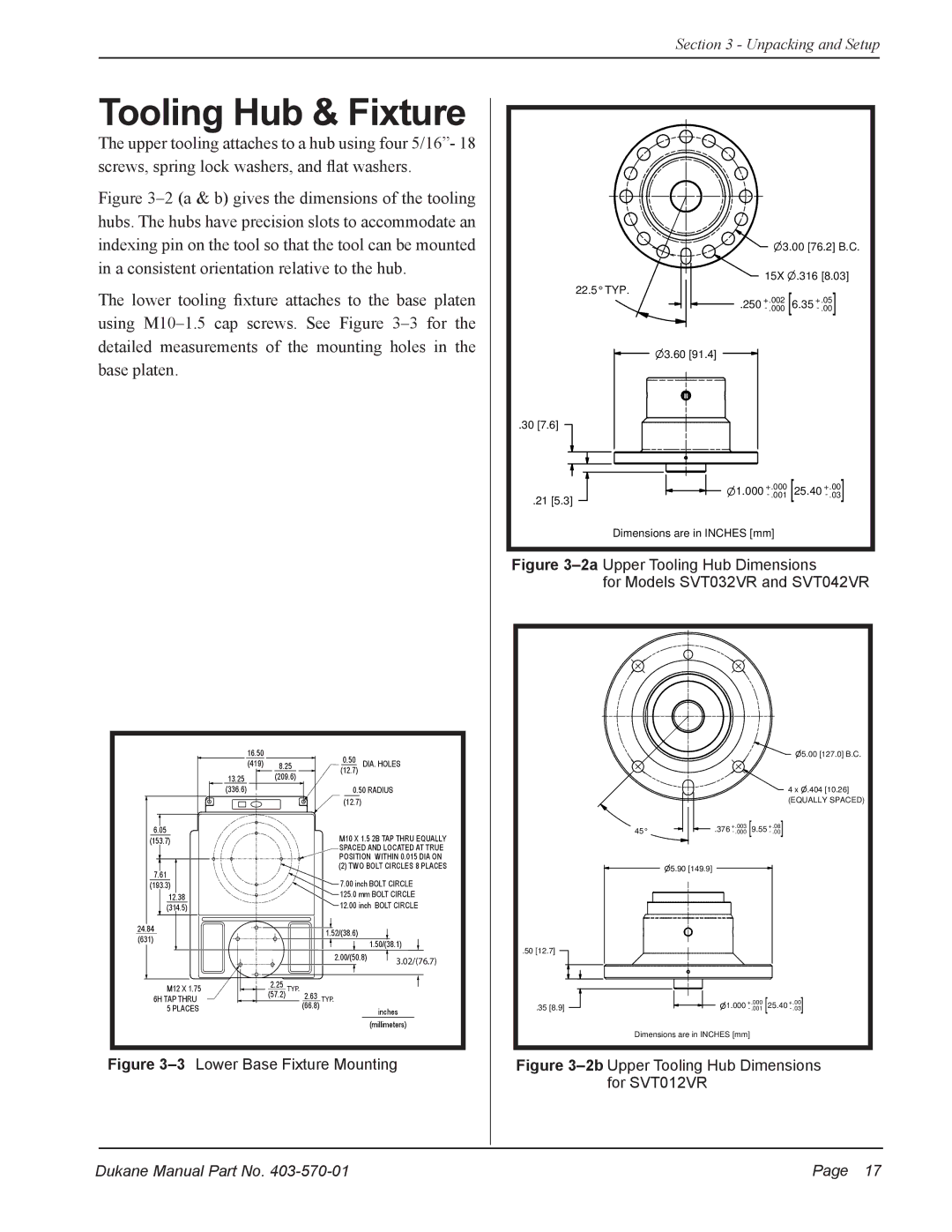
The upper tooling attaches to a hub using four 5/16”- 18 screws, spring lock washers, and flat washers.
Figure 3–2 (a & b) gives the dimensions of the tooling hubs. The hubs have precision slots to accommodate an indexing pin on the tool so that the tool can be mounted in a consistent orientation relative to the hub.
The lower tooling fixture attaches to the base platen using M10–1.5 cap screws. See Figure 3–3 for the detailed measurements of the mounting holes in the base platen.
3.00 [76.2] B.C.
15X .316 [8.03]
22.5° TYP.
.250
3.60 [91.4]
.30 [7.6]
.21 [5.3]
1.000
16.50 |
| 0.50 |
|
(419) | 8.25 | DIA. HOLES | |
13.25 | (209.6) | (12.7) |
|
|
| ||
(336.6) |
| 0.50 RADIUS | |
|
| (12.7) |
|
Dimensions are in INCHES [mm]
Figure 3–2a Upper Tooling Hub Dimensions
for Models SVT032VR and SVT042VR
5.00 [127.0] B.C.
4 x .404 [10.26]
(EQUALLY SPACED)
6.05 |
(153.7) |
7.61 |
(193.3) |
12.38 |
(314.5) |
24.84 |
(631) |
M12 X 1.75 |
6H TAP THRU
5 PLACES
|
| M10 X 1.5 2B TAP THRU EQUALLY | |
|
| SPACED AND LOCATED AT TRUE | |
|
| POSITION WITHIN 0.015 DIA ON | |
|
| (2) TWO BOLT CIRCLES 8 PLACES | |
|
| 7.00 inch BOLT CIRCLE | |
|
| 125.0 mm BOLT CIRCLE | |
|
| 12.00 inch BOLT CIRCLE | |
|
| 1.52/(38.6) |
|
|
|
| 1.50/(38.1) |
|
| 2.00/(50.8) | 3.02/(76.7) |
|
|
| |
2.25 | TYP. |
|
|
(57.2) | 2.63 | TYP. |
|
| (66.8) |
| inches |
|
|
| |
(millimeters)
45° |
|
|
| .376 |
|
|
5.90 [149.9]
.50 [12.7] |
|
.35 [8.9] | 1.000 |
Dimensions are in INCHES [mm]
Figure 3–3 Lower Base Fixture Mounting
Figure 3–2b Upper Tooling Hub Dimensions for SVT012VR
Dukane Manual Part No. | Page 17 |