Section 5 - Touch Screen Menus
RUN Mode
When the welder is first turned on after the
Screen Layout
The screen has the same basic layout for most of the selected operations. The STATUS icon indicates the ready state of the machine. To the right of the icon is the name of the currently loaded Setup File. Below the file name is the Message Area. The three mode select buttons on the left side below the status icon select either a Run mode (RUN), a Weld Setup screen (SETUP), or the Setup Utilities screen (TOOLS). The selected mode is indicated by a darkened button. The center of the screen displays the parameters from the last weld cycle. The Part Data button on the right displays a report of previously welded parts.
The screen shots on this page all show the RUN mode. The RUN screen is the default startup screen. This screen needs to be selected in order to initiate a weld cycle. Just below the PROCESS DATA label as shown in Figure
Figure 5–1 Startup Screen With E-Stop Cleared
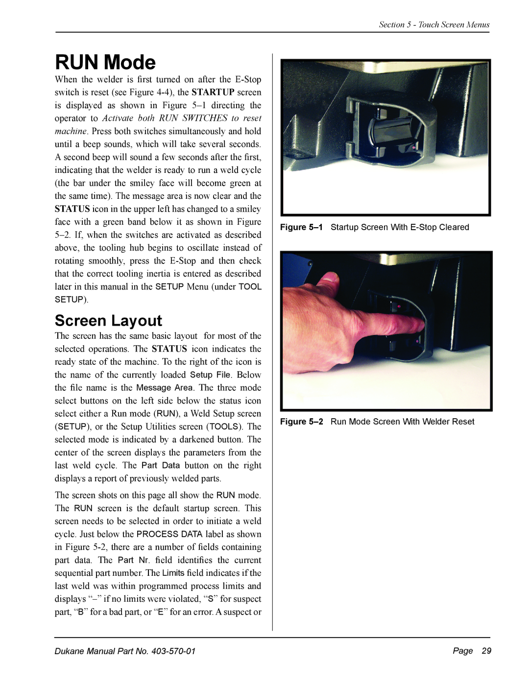
Figure 5–2 Run Mode Screen With Welder Reset
Dukane Manual Part No. | Page 29 |