Appendix A
Base Interface
Connector
The base interface connector is a DB
A schematic of the Operate and Abort switches connected through the base Interface Connector is shown in Figure
51
9 6
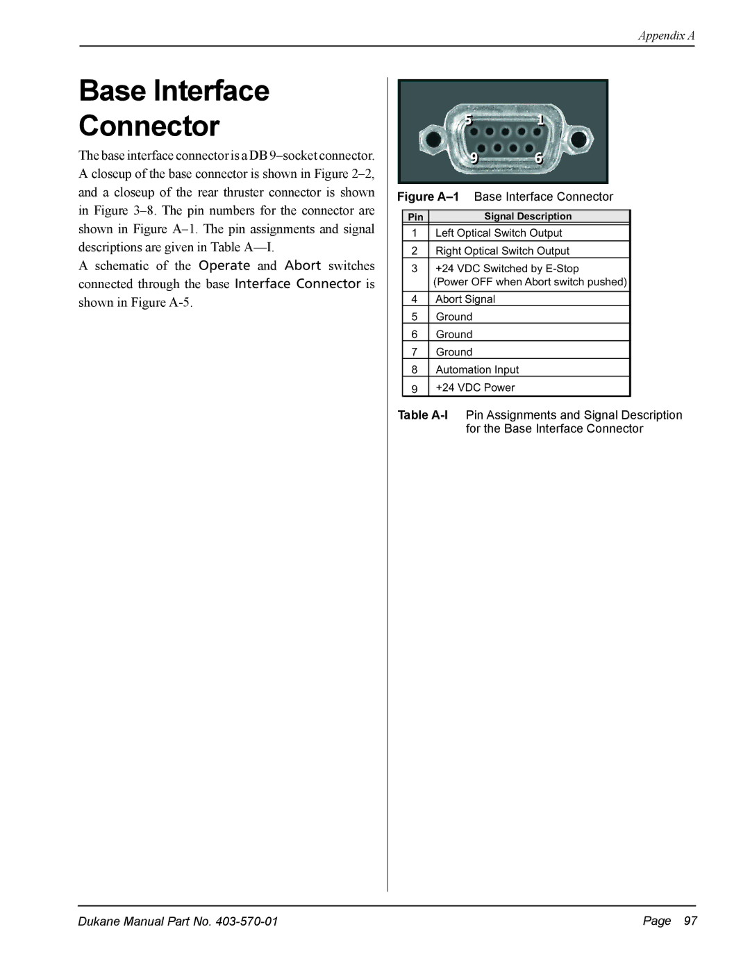
Figure A–1 Base Interface Connector
| Pin | Signal Description |
| 1 | Left Optical Switch Output |
|
|
|
| 2 | Right Optical Switch Output |
| 3 | +24 VDC Switched by |
(Power OFF when Abort switch pushed)
4Abort Signal
5Ground
6Ground
7Ground
8Automation Input
9+24 VDC Power
Table
Dukane Manual Part No. | Page 97 |