ETHERNET
. . . .CONNECTOR. . . . .
TE C H N I C A L SP E C I F I C A T I O N .S . Connectors and Pinouts ..
.
O U T P U T C A B L E S
Both the digital and analog outputs of the DGy 201x are provided on the graphics output connector. Purpose built cables are available commercially to provide connections for digital interfaces or analog interfaces. The DGy 201x is provided with DVI
C O N N E C T O R T Y P E A N D P I N O U T S
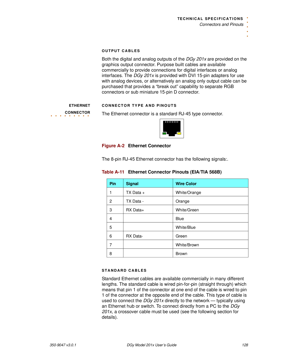
The Ethernet connector is a standard
Figure A-2 Ethernet Connector
The
Table A-11 Ethernet Connector Pinouts (EIA/TIA 568B)
Pin | Signal | Wire Color |
1 | TX Data + | White/Orange |
|
|
|
2 | TX Data - | Orange |
|
|
|
3 | RX Data+ | White/Green |
|
|
|
4 |
| Blue |
|
|
|
5 |
| White/Blue |
|
|
|
6 | RX Data- | Green |
|
|
|
7 |
| White/Brown |
|
|
|
8 |
| Brown |
|
|
|
S T A N D A R D C A B L E S
Standard Ethernet cables are available commercially in many different lengths. The standard cable is wired
DGy Model 201x User’s Guide | 128 |