I N S TA L L A T I O N A N D S E T U
.P
. Rear Panel ..
.
Important
Do not unlock while there is disk activity. This will cause loss of data.
•Disk Power Indicator
The Disk Power light indicates that power is applied to the removable disk drive. The power is disabled when the key lock is in the correct position to remove or install a drive. The drive cannot be removed or installed when this light is illuminated.
•Disk Indicator
The Disk activity light indicates read or write activity to the removable disk. Do not remove the drive while the disk is active.
REAR. . . . .PANEL. . . . . . . . . . . . . . . . . . . . . . . .
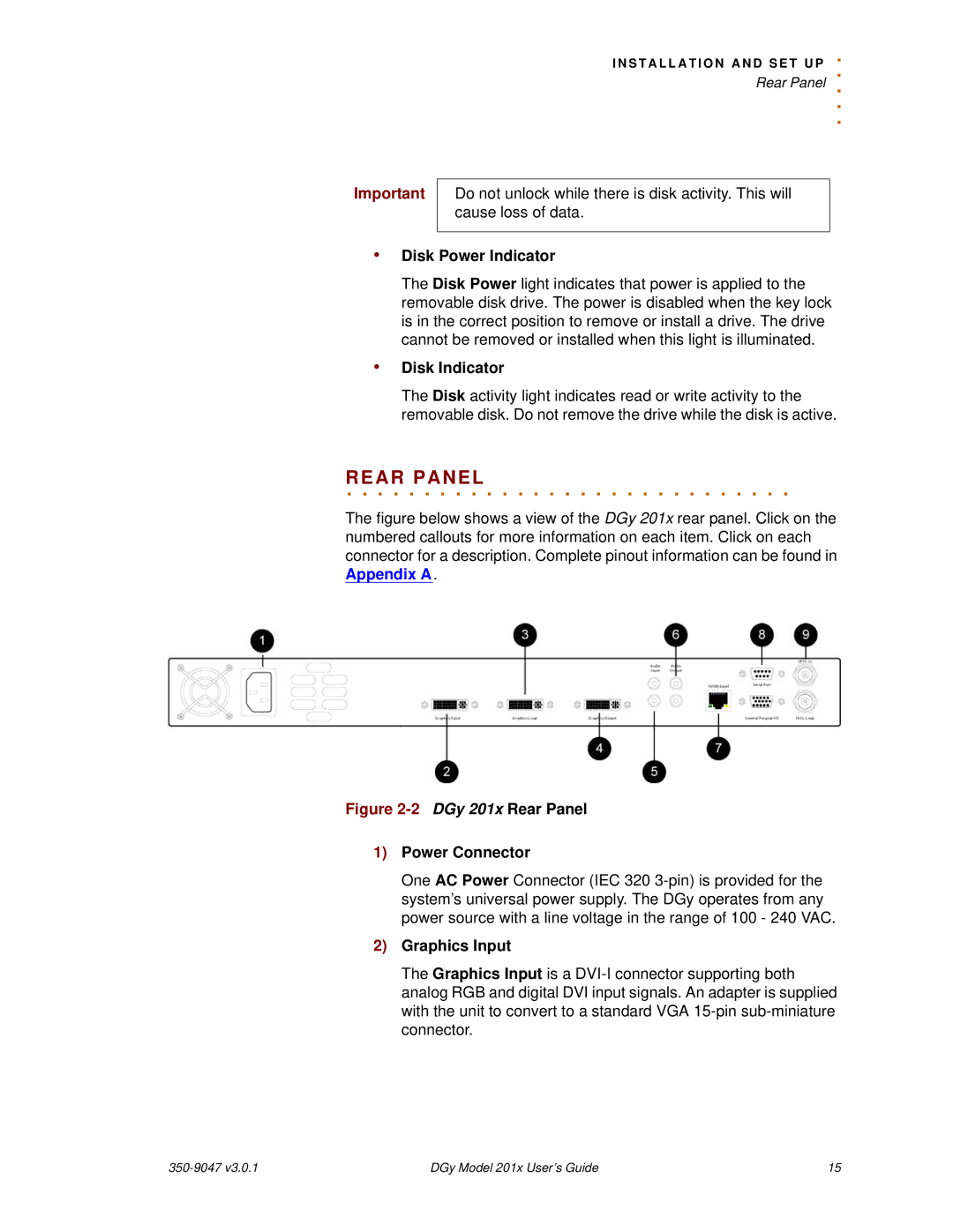
The figure below shows a view of the DGy 201x rear panel. Click on the numbered callouts for more information on each item. Click on each connector for a description. Complete pinout information can be found in Appendix A.
Figure 2-2 DGy 201x Rear Panel
1)Power Connector
One AC Power Connector (IEC 320
2)Graphics Input
The Graphics Input is a
| DGy Model 201x User’s Guide | 15 |