TE C H N I C A L SP E C I F I C A T I O N
.S
. Connectors and Pinouts ..
.
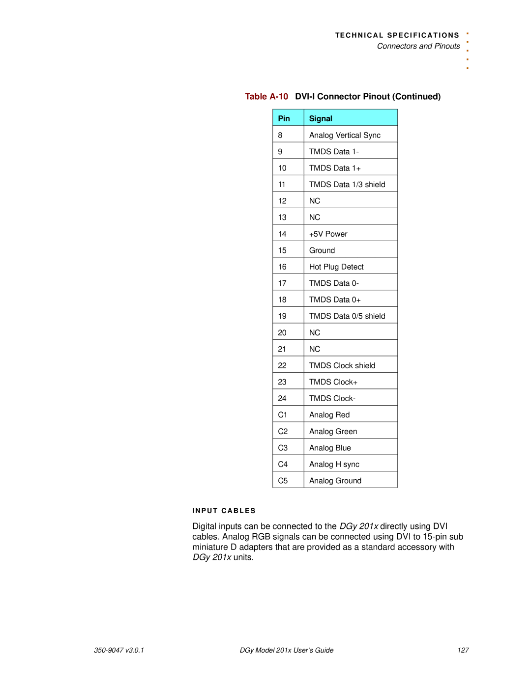
Table A-10 DVI-I Connector Pinout (Continued)
Pin | Signal |
8 | Analog Vertical Sync |
|
|
9 | TMDS Data 1- |
|
|
10 | TMDS Data 1+ |
|
|
11 | TMDS Data 1/3 shield |
|
|
12 | NC |
|
|
13 | NC |
|
|
14 | +5V Power |
|
|
15 | Ground |
|
|
16 | Hot Plug Detect |
|
|
17 | TMDS Data 0- |
|
|
18 | TMDS Data 0+ |
|
|
19 | TMDS Data 0/5 shield |
|
|
20 | NC |
|
|
21 | NC |
|
|
22 | TMDS Clock shield |
|
|
23 | TMDS Clock+ |
|
|
24 | TMDS Clock- |
|
|
C1 | Analog Red |
|
|
C2 | Analog Green |
|
|
C3 | Analog Blue |
|
|
C4 | Analog H sync |
|
|
C5 | Analog Ground |
|
|
I N P U T C A B L E S
Digital inputs can be connected to the DGy 201x directly using DVI cables. Analog RGB signals can be connected using DVI to
DGy Model 201x User’s Guide | 127 |