TE C H N I C A L SP E C I F I C A T I O N
.S
|
| . |
|
| Connectors and Pinouts |
|
| . . . |
| CONNECTORS AND PINOUTS | |
| . . . . . . . . . . . . . . . . . . . . . . . . . . . . . | |
| This section provides information about the signal and control | |
| connectors used in DGy 201x. | |
| • | |
| • | Ethernet Connector |
| • | Ethernet Connector |
| • | |
. . . . . . . . . | The DVI connector is used to interconnect graphics devices. This is a | |
standard connector based on the work of the Digital Display Working Group (DDWG).
C O N N E C T O R T Y P E A N D P I N O U T S
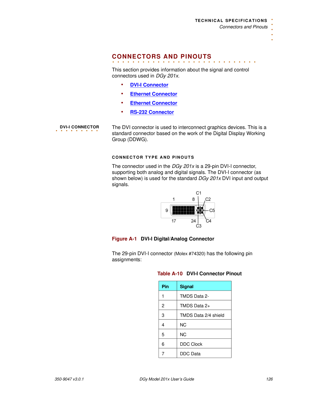
The connector used in the DGy 201x is a
Figure A-1 DVI-I Digital/Analog Connector
The
Table A-10 DVI-I Connector Pinout
Pin | Signal |
1 | TMDS Data 2- |
|
|
2 | TMDS Data 2+ |
|
|
3 | TMDS Data 2/4 shield |
|
|
4 | NC |
|
|
5 | NC |
|
|
6 | DDC Clock |
|
|
7 | DDC Data |
|
|
DGy Model 201x User’s Guide | 126 |