I N S TA L L A T I O N A N D S E T U
.P
. Front Panel ..
.
Important
Do not use the DGy 201x as a shelf to support other pieces of equipment as this may cause damage to the rack ears and mounting screws.
•The DGy 201x is provided with a rear rack bracket and arm to support the rear of the chassis. It is recommended that the bracket be used to provide additional stability.
•Attach the rear brackets to the rack adapter at the rear of the chassis.
•Slide an arm through the slot on the rack adapter and attach the arm to the chassis.
•Attach the arm to the rear bracket by means of the fasteners located in the arms.
FRONT. . . . . .PANEL. . . . . . . . . . . . . . . . . . . . . . .
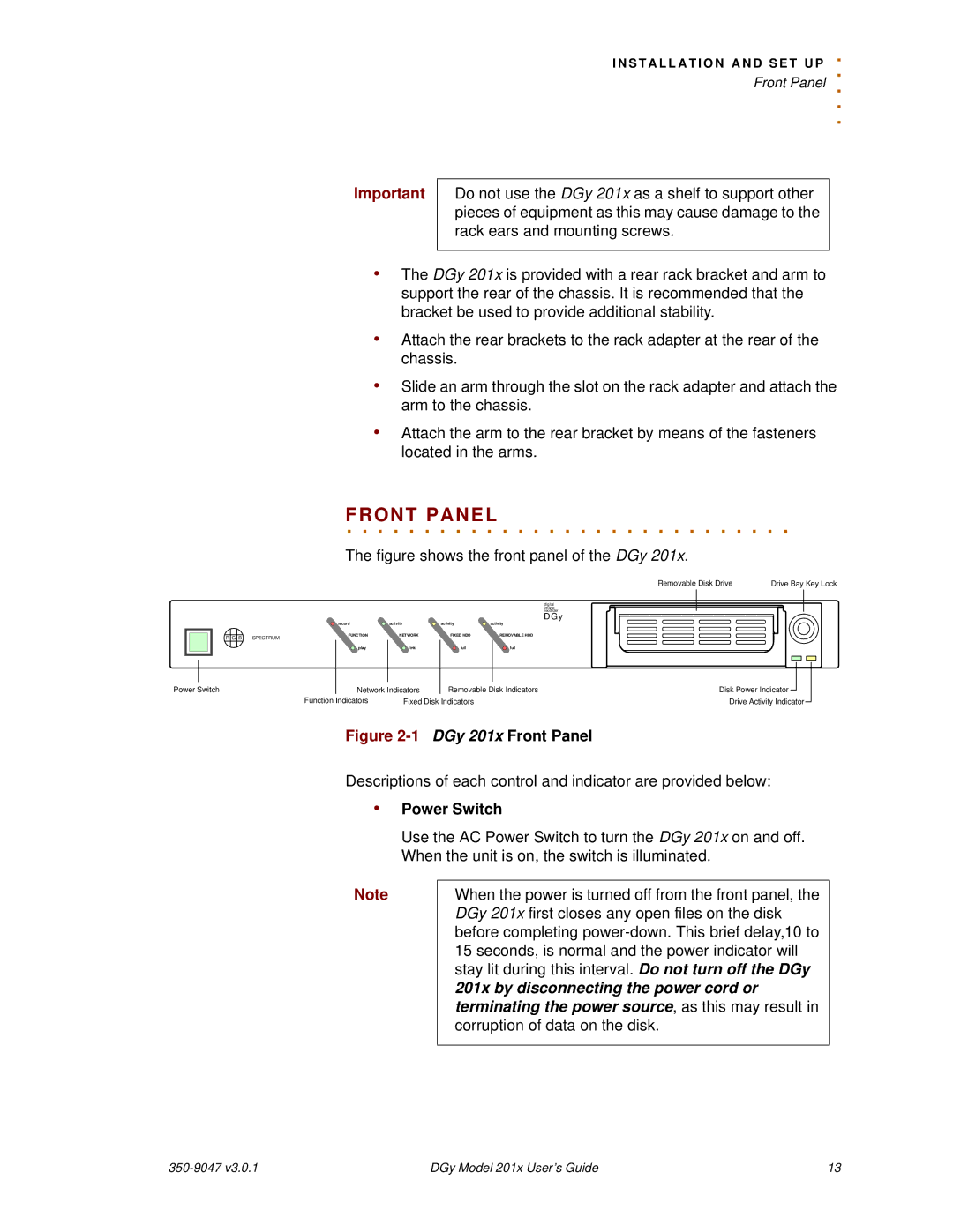
The figure shows the front panel of the DGy 201x.
Removable Disk Drive | Drive Bay Key Lock |
digital |
|
image |
|
recorder |
|
DGy |
|
|
| record | activity | activity | activity |
R G | B SPECTRUM | FUNCTION | NETWORK | FIXED HDD | REMOVABLE HDD |
|
|
|
| ||
|
| play | link | full | full |
|
|
|
|
|
|
|
|
|
|
|
|
|
|
|
|
Power Switch | Network Indicators | Removable Disk Indicators | Disk Power Indicator |
|
| ||
|
| ||||||
|
| Function Indicators | Fixed Disk Indicators | Drive Activity Indicator | |||
Figure 2-1 DGy 201x Front Panel
Descriptions of each control and indicator are provided below:
•Power Switch
Use the AC Power Switch to turn the DGy 201x on and off. When the unit is on, the switch is illuminated.
Note
When the power is turned off from the front panel, the DGy 201x first closes any open files on the disk before completing
| DGy Model 201x User’s Guide | 13 |