Do not stack more than three connector blocks together on any GPIB connector. The resultant leverage can exert excessive force on the mounting panels. Make sure that all connectors are fully seated and that the lock screws are firmly hand- tightened. Use a screwdriver only for the removal of the screws.
GPIB Address
The GPIB address of the Electronic Load is factory set to address 5. The GPIB address can only be set using the front panel ![]() and ENTRY keys. Chapter 4 explains how to change the GPIB address.
and ENTRY keys. Chapter 4 explains how to change the GPIB address.
Rear Panel Connectors and Switches
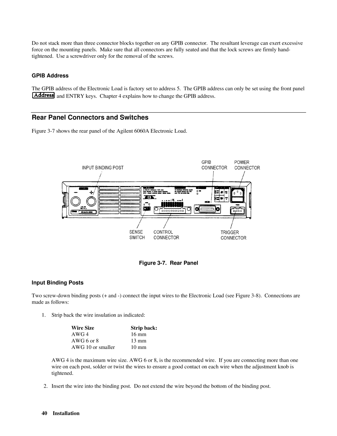
Figure 3-7 shows the rear panel of the Agilent 6060A Electronic Load.
Figure 3-7. Rear Panel
Input Binding Posts
Two
1.Strip back the wire insulation as indicated:
Wire Size | Strip back: |
AWG 4 | 16 mm |
AWG 6 or 8 | 13 mm |
AWG 10 or smaller | 10 mm |
AWG 4 is the maximum wire size. AWG 6 or 8, is the recommended wire. If you are connecting more than one wire on each post, solder or twist the wires to ensure a good contact on each wire when the adjustment knob is tightened.
2. Insert the wire into the binding post. Do not extend the wire beyond the bottom of the binding post.
40 Installation