Location and Cooling
Table 1-1 gives the dimensions of the Electronic Load. The cabinet has plastic feet that are shaped to ensure self-alignment when stacked with other Agilent System II cabinets. The feet may be removed for rack mounting. Your Electronic Load must be installed in a location that allows sufficient space at the sides and rear of the unit for adequate air circulation.
The unit can be mounted in a standard 19-inch rack panel or enclosure. Rack mount kits are available as option numbers 908 and 909 (with handles). Installation instructions are included with each rack mounting kit. Instrument support rails are recommended for non-stationary installations.
The unit can operate without loss of performance within the temperature range of 0° to 40°C, and with derated performance from 40° to 55° C. A variable-speed fan cools the unit by drawing in air through the sides and exhausting it out the back. Using Agilent rack mount or slide kits will not impede the flow of air.
Turn-On Checkout
The simplified turn-on checkout procedure discussed in this section verifies that about 90% of the Electronic Load is operating correctly. The Service Manual (Option 910) contains detailed performance and verification tests. Before connecting the power cord and turning on the Electronic Load, check that the line voltage is set correctly and that the sense switch is set to Local.
Check Line Voltage
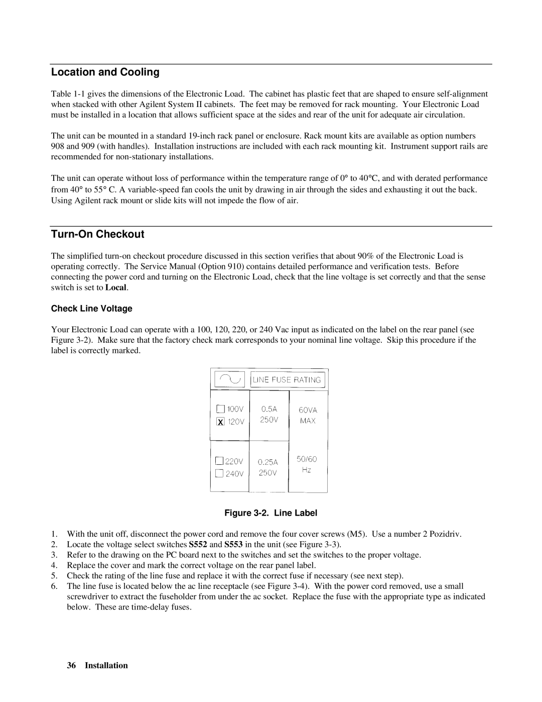
Your Electronic Load can operate with a 100, 120, 220, or 240 Vac input as indicated on the label on the rear panel (see Figure 3-2). Make sure that the factory check mark corresponds to your nominal line voltage. Skip this procedure if the label is correctly marked.
Figure 3-2. Line Label
1.With the unit off, disconnect the power cord and remove the four cover screws (M5). Use a number 2 Pozidriv.
2.Locate the voltage select switches S552 and S553 in the unit (see Figure 3-3).
3.Refer to the drawing on the PC board next to the switches and set the switches to the proper voltage.
4.Replace the cover and mark the correct voltage on the rear panel label.
5.Check the rating of the line fuse and replace it with the correct fuse if necessary (see next step).
6.The line fuse is located below the ac line receptacle (see Figure 3-4). With the power cord removed, use a small screwdriver to extract the fuseholder from under the ac socket. Replace the fuse with the appropriate type as indicated below. These are time-delay fuses.