3
Installation
Introduction
This chapter discusses how to install and make connections to the rear panel of your Electronic Load. A
Inspection
When you receive your Electronic Load, inspect it for any obvious damage that may have occurred during shipment. If there is damage, notify the carrier immediately and notify the nearest Agilent Sales Office. Warranty information is printed on the inside front cover of this manual.
Save the shipping cartons and packing materials in case the unit must be returned to Agilent Technologies in the future. If you return the unit for service, attach a tag identifying the owner and model number. Also include a brief description of the problem. In addition to this manual, check that the following items have been received with your Electronic Load:
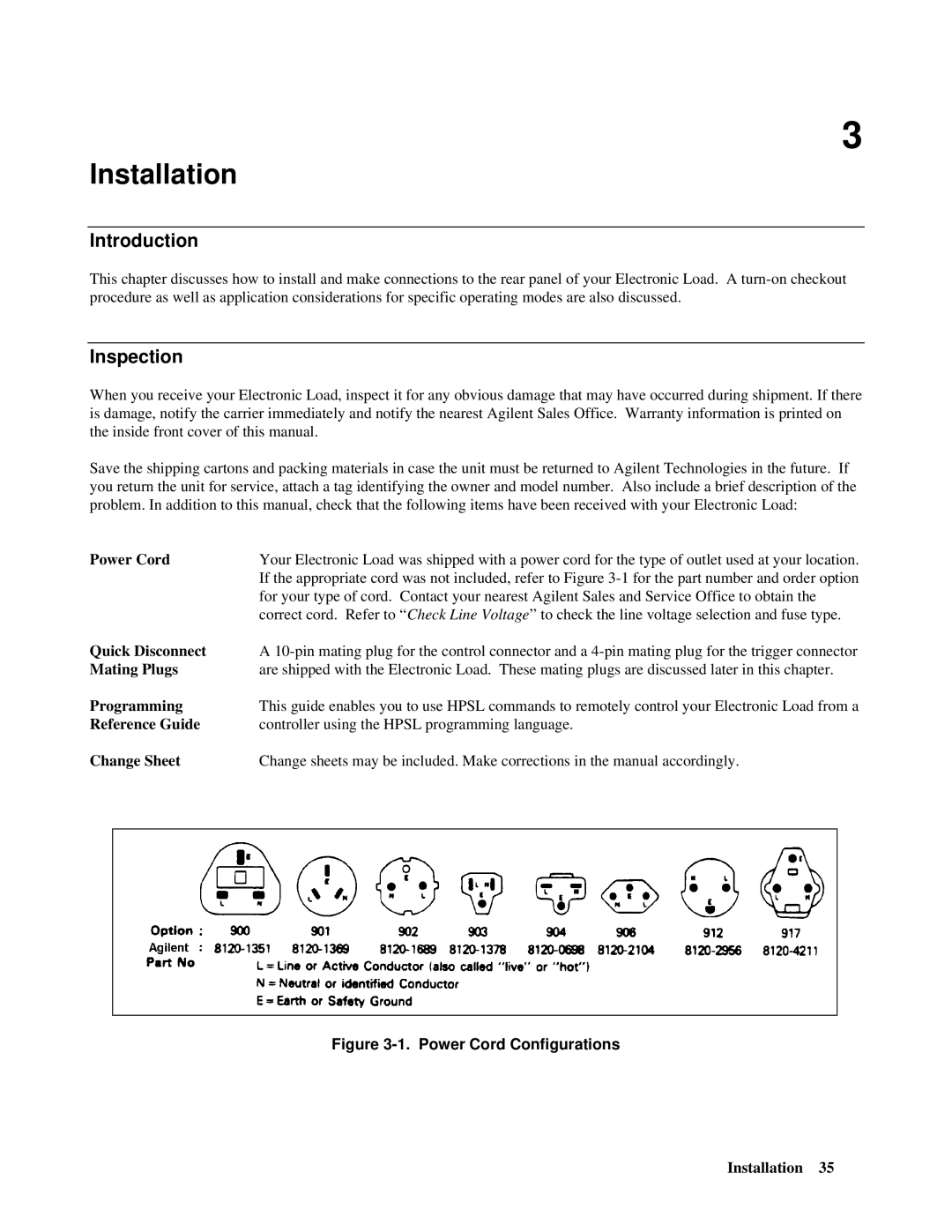
Power Cord | Your Electronic Load was shipped with a power cord for the type of outlet used at your location. | ||
|
| If the appropriate cord was not included, refer to Figure | |
|
| for your type of cord. Contact your nearest Agilent Sales and Service Office to obtain the | |
|
| correct cord. Refer to “ Check Line Voltage” to check the line voltage selection and fuse type. | |
Quick Disconnect | A | ||
Mating Plugs | are shipped with the Electronic Load. These mating plugs are discussed later in this chapter. | ||
Programming | This guide enables you to use HPSL commands to remotely control your Electronic Load from a | ||
Reference Guide | controller using the HPSL programming language. | ||
Change Sheet | Change sheets may be included. Make corrections in the manual accordingly. | ||
|
|
|
|
Figure 3-1. Power Cord Configurations
Installation 35
