Trigger Connector
A
Consistent with good engineering practice, all leads connected to the trigger connector should be twisted and shielded to maintain the instrument’s specified performance.
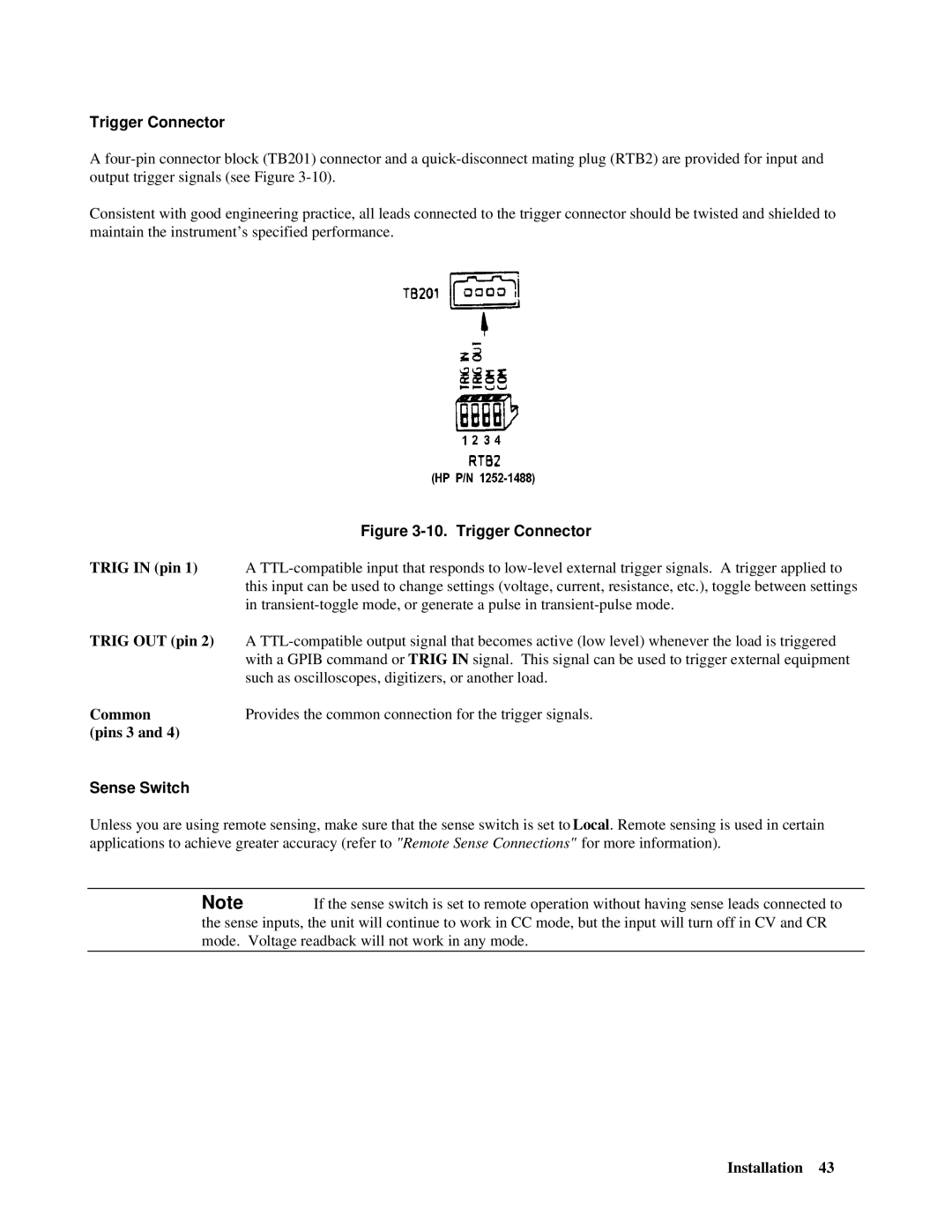
Figure 3-10. Trigger Connector
TRIG IN (pin 1) A
TRIG OUT (pin 2) A
CommonProvides the common connection for the trigger signals.
(pins 3 and 4)
Sense Switch
Unless you are using remote sensing, make sure that the sense switch is set to Local. Remote sensing is used in certain applications to achieve greater accuracy (refer to "Remote Sense Connections" for more information).
Note If the sense switch is set to remote operation without having sense leads connected to the sense inputs, the unit will continue to work in CC mode, but the input will turn off in CV and CR mode. Voltage readback will not work in any mode.
Installation 43