TMT1HNCR specifications
The Toto TMT1HNCR is a remarkable innovation in the realm of modern bathroom solutions, particularly noted for its exceptional performance as a high-efficiency toilet. Designed with a blend of style and functionality, this model exemplifies Toto’s commitment to quality and innovation in bathroom sanitary ware.One of the standout features of the TMT1HNCR is its Tornado Flush system. This advanced flushing technology utilizes a powerful, swift, and efficient flush that employs a centrifugal force, ensuring that the bowl is cleaned effectively with every use. The Tornado Flush system not only maximizes waste removal but also minimizes water consumption, making it an environmentally friendly choice. With a flush rate of just 1.28 gallons per flush (GPF), this toilet meets rigorous water-saving standards without compromising performance.
Another key characteristic of the TMT1HNCR is its special CeFiONtect glaze, which is applied to the toilet bowl's surface. This innovative coating allows for a smoother surface that prevents debris and mold from sticking, ensuring that the toilet stays cleaner for longer and makes cleaning significantly easier. The properties of CeFiONtect help to keep the toilet hygienic and reduce the frequency of deep cleaning, providing a more maintenance-free experience for users.
The TMT1HNCR also features a sleek, modern design that seamlessly fits into any contemporary bathroom aesthetic. Its elongated bowl offers added comfort, while the compact profile maximizes usable space in smaller bathrooms. The height is optimized for user convenience, accommodating a wide range of users and enhancing accessibility.
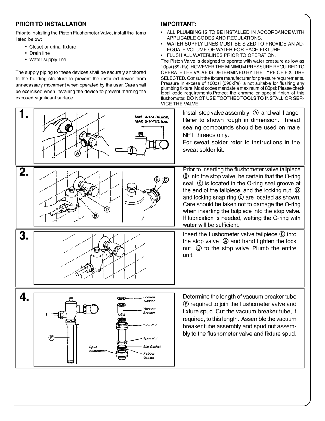
In terms of installation, the Toto TMT1HNCR is designed for easy and straightforward setup, featuring a one-piece construction that eliminates the need for separate tank and bowl installation. This not only enhances its aesthetic appeal but also simplifies maintenance, making it a practical choice for homeowners and contractors alike.
In conclusion, the Toto TMT1HNCR stands out as a top-tier toilet solution with its intelligent flushing technology, hygienic features, elegant design, and user-friendly installation. The blend of efficiency and style makes it a superior option for those seeking to modernize their bathroom while contributing to water conservation efforts. With its array of innovative features, the TMT1HNCR truly embodies the quality and excellence associated with the Toto brand.

