|
|
| 2.5” Solid State Disk | ||||
|
|
|
| ||||
|
|
|
|
|
|
| |
|
|
|
|
|
|
| |
|
|
|
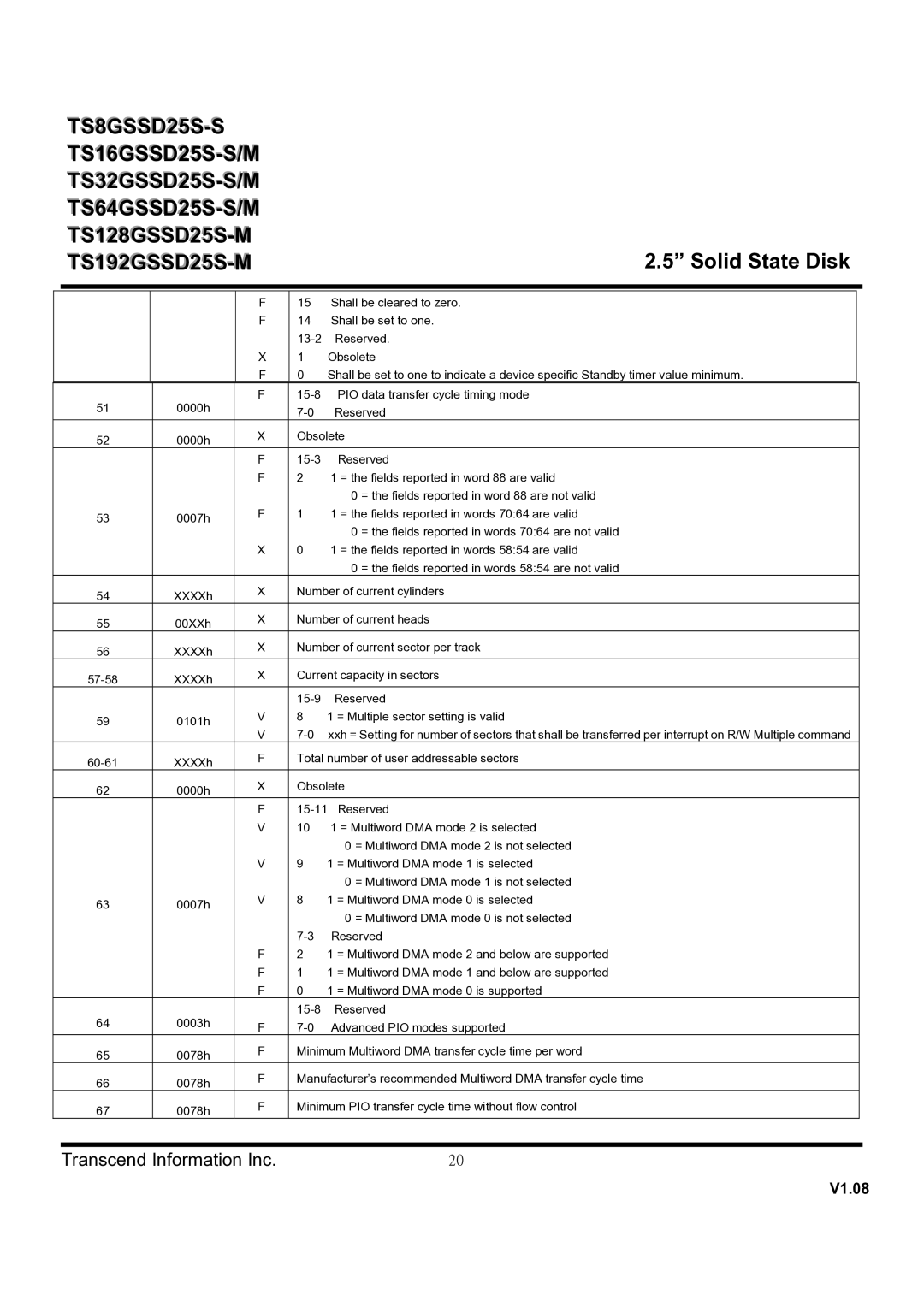
| F | 15 Shall be cleared to zero. |
| |
|
|
|
| F | 14 Shall be set to one. |
| |
|
|
|
|
| Reserved. |
| |
|
|
|
| X | 1 | Obsolete |
|
|
|
|
| F | 0 | Shall be set to one to indicate a device specific Standby timer value minimum. |
|
| 51 | 0000h |
| F |
|
| |
|
|
| Reserved |
| |||
|
|
|
|
|
| ||
| 52 | 0000h |
| X | Obsolete |
| |
|
|
|
|
|
| ||
|
|
|
| F | Reserved |
| |
|
|
|
| F | 2 | 1 = the fields reported in word 88 are valid |
|
|
|
|
|
|
| 0 = the fields reported in word 88 are not valid |
|
| 53 | 0007h |
| F | 1 | 1 = the fields reported in words 70:64 are valid |
|
|
|
|
| 0 = the fields reported in words 70:64 are not valid |
| ||
|
|
|
|
|
|
| |
|
|
|
| X | 0 | 1 = the fields reported in words 58:54 are valid |
|
|
|
|
|
|
| 0 = the fields reported in words 58:54 are not valid |
|
| 54 | XXXXh |
| X | Number of current cylinders |
| |
|
|
|
|
|
| ||
| 55 | 00XXh |
| X | Number of current heads |
| |
|
|
|
|
|
| ||
| 56 | XXXXh |
| X | Number of current sector per track |
| |
|
|
|
|
|
| ||
| XXXXh |
| X | Current capacity in sectors |
| ||
|
|
|
|
|
| ||
|
|
|
|
| Reserved |
| |
| 59 | 0101h |
| V | 8 | 1 = Multiple sector setting is valid |
|
|
| V |
| ||||
|
|
|
|
| |||
| XXXXh |
| F | Total number of user addressable sectors |
| ||
|
|
|
|
|
| ||
| 62 | 0000h |
| X | Obsolete |
| |
|
|
|
|
|
| ||
|
|
|
| F |
| ||
|
|
|
| V | 10 1 = Multiword DMA mode 2 is selected |
| |
|
|
|
|
|
| 0 = Multiword DMA mode 2 is not selected |
|
|
|
|
| V | 9 | 1 = Multiword DMA mode 1 is selected |
|
|
|
|
|
|
| 0 = Multiword DMA mode 1 is not selected |
|
| 63 | 0007h |
| V | 8 | 1 = Multiword DMA mode 0 is selected |
|
|
|
|
| 0 = Multiword DMA mode 0 is not selected |
| ||
|
|
|
|
|
|
| |
|
|
|
|
| Reserved |
| |
|
|
|
| F | 2 | 1 = Multiword DMA mode 2 and below are supported |
|
|
|
|
| F | 1 | 1 = Multiword DMA mode 1 and below are supported |
|
|
|
|
| F | 0 | 1 = Multiword DMA mode 0 is supported |
|
| 64 | 0003h |
|
| Reserved |
| |
|
| F |
| ||||
|
|
|
|
| |||
| 65 | 0078h |
| F | Minimum Multiword DMA transfer cycle time per word |
| |
|
|
|
|
|
| ||
| 66 | 0078h |
| F | Manufacturer’s recommended Multiword DMA transfer cycle time |
| |
|
|
|
|
|
| ||
| 67 | 0078h |
| F | Minimum PIO transfer cycle time without flow control |
| |
|
|
|
|
|
| ||
|
|
|
|
|
|
|
|
| Transcend Information Inc. |
| 20 |
| |||
