Installation -- Continued
AutoCross jumper
The AutoCross jumper is located on the media converter’s circuit board (labeled NA = No Autocross; A = AutoCross). See Jumper position below.
Install the slide-in-module
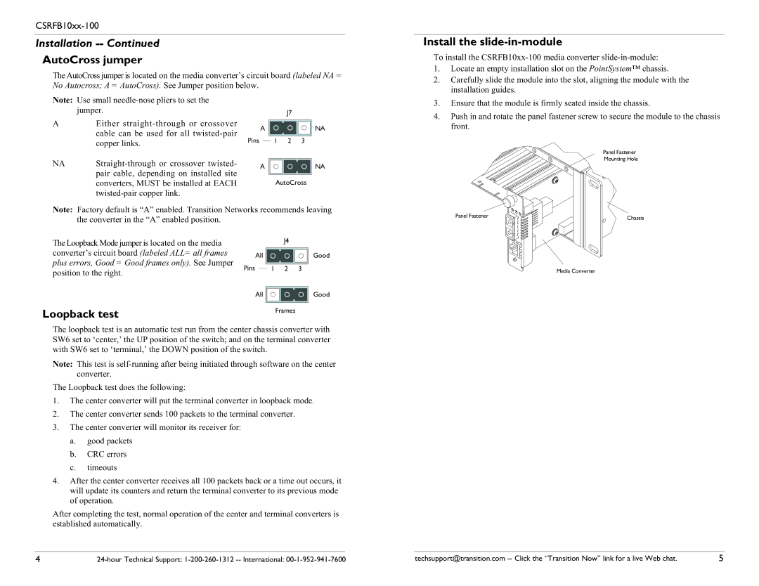
To install the
1. | Locate an empty installation slot on the PointSystem™ chassis. |
2. | Carefully slide the module into the slot, aligning the module with the |
| installation guides. |
Note: Use small
AEither
NA | |
| pair cable, depending on installed site |
| converters, MUST be installed at EACH |
|
A
Pins
A
J7
NA
1 2 3
NA
AutoCross
3. | Ensure that the module is firmly seated inside the chassis. |
4. | Push in and rotate the panel fastener screw to secure the module to the chassis |
| front. |
Panel Fastener
Mounting Hole
Note: Factory default is “A” enabled. Transition Networks recommends leaving the converter in the “A” enabled position.
The Loopback Mode jumper is located on the media |
|
|
| J4 | ||
|
|
|
|
|
| |
converter’s circuit board (labeled ALL= all frames | All |
|
|
| Good | |
plus errors, Good = Good frames only). See Jumper | Pins |
|
|
|
|
|
| 1 2 3 |
| ||||
position to the right. |
|
| ||||
|
|
|
|
|
| |
|
|
|
|
|
|
|
| All |
|
|
| Good | |
Loopback test |
|
| Frames |
| ||
|
|
|
|
|
| |
The loopback test is an automatic test run from the center chassis converter with SW6 set to ‘center,’ the UP position of the switch; and on the terminal converter with SW6 set to ‘terminal,’ the DOWN position of the switch.
Note: This test is
The Loopback test does the following:
1.The center converter will put the terminal converter in loopback mode.
2.The center converter sends 100 packets to the terminal converter.
3.The center converter will monitor its receiver for:
a.good packets
b.CRC errors
c.timeouts
4.After the center converter receives all 100 packets back or a time out occurs, it will update its counters and return the terminal converter to its previous mode of operation.
After completing the test, normal operation of the center and terminal converters is established automatically.
Panel Fastener | Chassis |
|
Media Converter
4 | techsupport@transition.com | 5 |