Installation
CAUTION: Wear a grounding converter and observe electrostatic discharge precautions while handling the media converter. Failure to observe this caution could result in damage to or failure of the media converter.
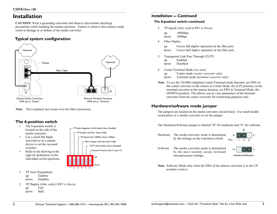
Typical system configuration
Network
Chassis | Network |
| Fiber Cable |
Chassis Center Converter | Remote Terminal Converter |
SW6 set to ‘Center’ | SW6 set to ‘Terminal’ |
Note: The Loopback test occurs over the fiber connection.
Installation -- Continued
The 6-position switch--continued
3.TP Speed (Only valid if SW1 is Down)
up 100Mbps down 10Mbps
4.Fiber Duplex
up | Forces full duplex operation on the fiber port. |
down | Forces half duplex operation on the fiber port. |
5.Transparent Link Pass Through (TLPT)
up Enabled down Disabled
6.Center/Terminal Mode (see note)
up | Center mode (center converter only) |
down | Terminal mode (terminal converter only) |
Note: To use the TS1000 compliant Center/Terminal mode function, set SW6 on the center converter in the chassis to Center Mode, the (UP) position; on the terminal converter at the remote location, set SW6 to Terminal Mode, the (DOWN) position. This allows you to view parameters of the terminal converter from the center converter for monitoring purposes only .
Hardware/software mode jumper
The jumpers are located on the media converter circuit board. Use small needle- nosed pliers or a similar converter to set the jumper.
The 6-position switch
•The
•Use a small flat blade screwdriver or a similar device to set the recessed switches.
•Refer to the drawing to the right for definitions of the individual switch positions.
TP
TP Speed (Up=100Mbs, Down=10Mbs)
Fiber Duplex (Up=Full, Down=Half)
TLPT (Up=Enabled, Down=Disabled)
![]() Center/Terminal (Up=C, Down=T)
Center/Terminal (Up=C, Down=T)
UP
Down
1 | 2 | 3 | 4 | 5 | 6 |
The Hardware/Software jumper is labeled “H” for hardware and “S” for software.
|
|
|
|
|
| J6 | ||
Hardware | The media converter mode is determined |
| H |
|
|
| S | |
|
|
|
| |||||
| by the settings on the | Pins |
|
| 1 | 2 3 |
| |
Software | The media converter mode is determined |
|
|
| ||||
| H |
|
|
| S | |||
|
|
|
| |||||
| by the most recently saved, |
|
|
|
| |||
|
|
|
|
|
|
|
| |
|
| Hardware/Software | ||||||
| microprocessor settings. |
| ||||||
Note: Software Mode only when the SW6 of the chassis converter is in the UP position (center).
1.TP
up Enables down Disables
2.TP Duplex (Only valid if SW1 is Down)
up Full down Half
2 | techsupport@transition.com | 3 |