J/FE-CF-03
Installation -- Continued
Power the media converter
AC power:
1.Install the power adapter cord to the back of the media converter.
2.Connect the power adapter plug to AC power.
3.Verify that the media converter is powered by observing the illuminated LED power indicator light.
DC power:
Consult the User’s Guide for the Transition Networks SPS1872-xx DC External Power Supply for powering the media converter.
Operation
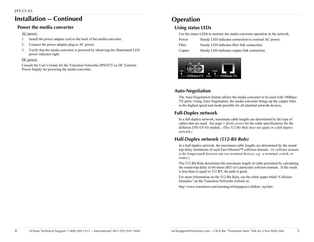
Using status LEDs
Use the status LEDs to monitor the media converter operation in the network.
| Power | | Steady LED indicates connection to external AC power. |
| Fiber | | Steady LED indicates fiber link connection. |
| Copper | | Steady LED indicates copper link connection. |
| | | | | | | | | | | | | | | | | | | | | |
| | | | | | | | | | | | | | | | | | | | | |
| | | | TX | | RX | | | | | | | | | | |
| | | | | | | | | | | | | | |
| Fiber | | | | | | | | | | | Copper | | | | | | | | | |
| | | | | | | | | | | | | | | | | | | |
| | 100Base-FX Power | 100Base-TX | |
| | | | | | | | | | | | | | | | | | | | | |
| | | | | | | | | | | | | | | | | | | | | |
Auto-Negotiation
The Auto-Negotiation feature allows the media converter to be used with 100Base- TX ports. Using Auto-Negotiation, the media converter brings up the copper links in the highest speed and mode possible for all attached network devices.
Full-Duplex network
In a full-duplex network, maximum cable lengths are determined by the type of cables that are used. See page 1 (front cover) for the cable specifications for the different J/FE-CF-03 models. (The 512-Bit Rule does not apply in a full-duplex network.)
Half-Duplex network (512-Bit Rule)
In a half-duplex network, the maximum cable lengths are determined by the round trip delay limitations of each Fast Ethernet™ collision domain. (A collision domain is the longest path between any two terminal devices, e.g. a terminal, switch, or router.)
The 512-Bit Rule determines the maximum length of cable permitted by calculating the round-trip delay in bit-times (BT) of a particular collision domain. If the result is less than or equal to 512 BT, the path is good.
For more information on the 512-Bit Rule, see the white paper titled “Collision Domains” on the Transition Networks website at:
http://www.transition.com/learning/whitepapers/colldom_wp.htm