Installation
CAUTION: Do Not install the
Jumper (shunt)
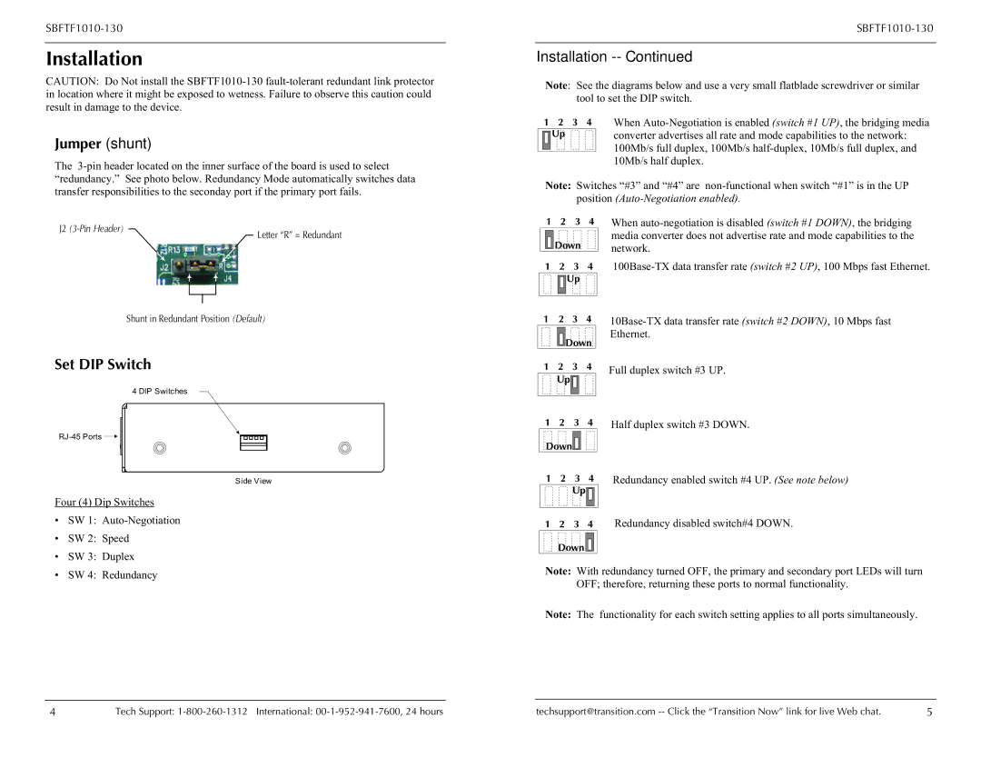
The
Installation -- Continued
Note: See the diagrams below and use a very small flatblade screwdriver or similar tool to set the DIP switch.
1 2 3 4 |
| When | ||
|
| Up |
| converter advertises all rate and mode capabilities to the network: |
|
|
|
| 100Mb/s full duplex, 100Mb/s |
|
|
|
| |
|
|
|
| |
|
|
|
| 10Mb/s half duplex. |
Note: Switches “#3” and “#4” are
J2
Letter “R” = Redundant
1 2 3 4
![]()
![]()
![]()
![]() Down
Down
1 2 3 4
![]()
![]()
![]()
![]() Up
Up
When
Shunt in Redundant Position (Default)
Set DIP Switch
4 DIP Switches
1 2 3 4
![]()
![]()
![]()
![]() Down
Down
1 | 2 | 3 | 4 |
| Up |
|
|
Full duplex switch #3 UP.
![]()
Side View
Four (4) Dip Switches
•SW 1:
•SW 2: Speed
•SW 3: Duplex
•SW 4: Redundancy
1 | 2 | 3 | 4 | Half duplex switch #3 DOWN. |
Down |
|
|
| |
1 | 2 | 3 | 4 | Redundancy enabled switch #4 UP. (See note below) |
|
| Up |
|
|
1 2 3 4 Redundancy disabled switch#4 DOWN.
Down ![]()
![]()
![]()
![]()
Note: With redundancy turned OFF, the primary and secondary port LEDs will turn OFF; therefore, returning these ports to normal functionality.
Note: The functionality for each switch setting applies to all ports simultaneously.
4 | Tech Support: | techsupport@transition.com | 5 |
