Diagnostic LEDs
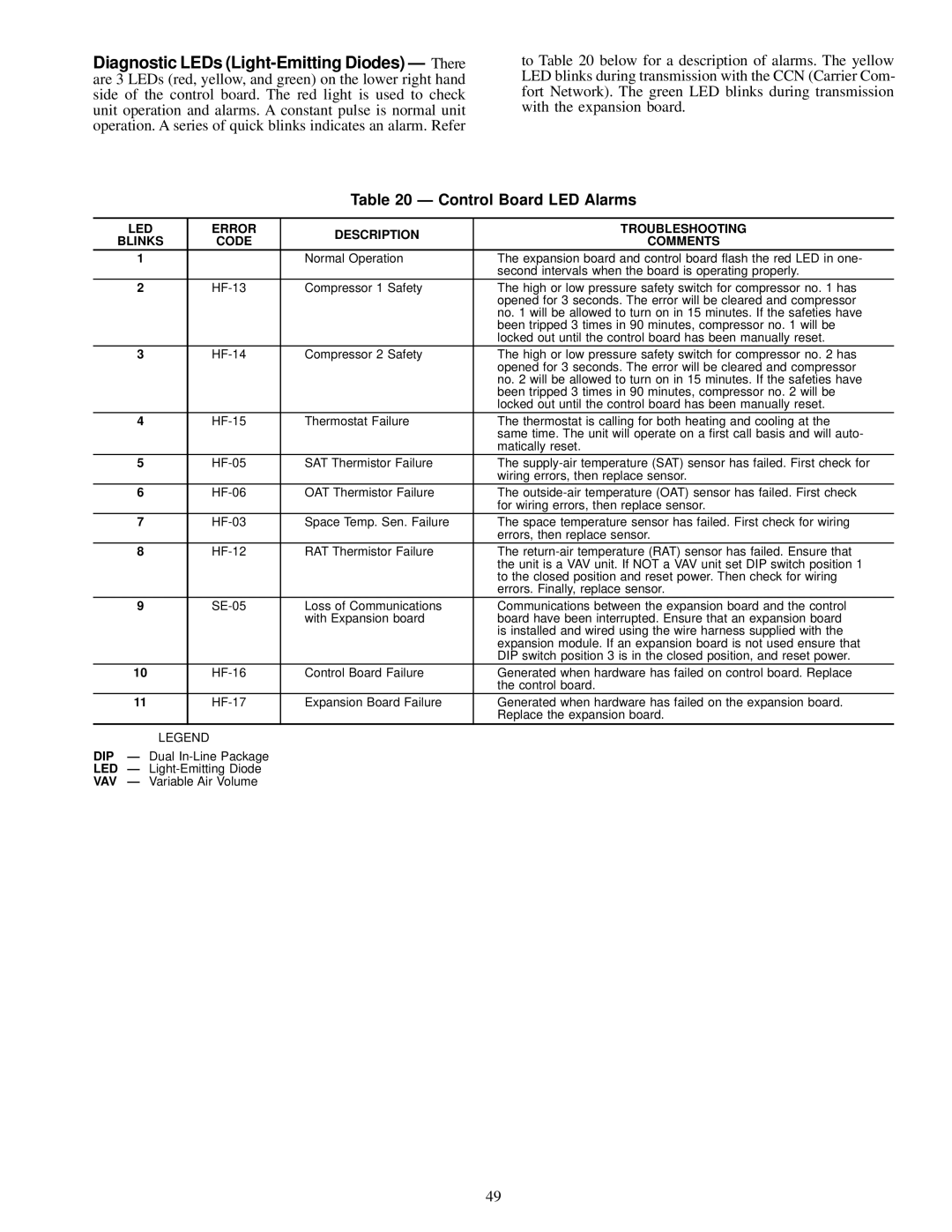
to Table 20 below for a description of alarms. The yellow LED blinks during transmission with the CCN (Carrier Com- fort Network). The green LED blinks during transmission with the expansion board.
Table 20 Ð Control Board LED Alarms
| LED |
| ERROR | DESCRIPTION | TROUBLESHOOTING |
| BLINKS |
| CODE | COMMENTS | |
|
|
| |||
| 1 |
|
| Normal Operation | The expansion board and control board ¯ash the red LED in one- |
|
|
|
|
| second intervals when the board is operating properly. |
| 2 |
| Compressor 1 Safety | The high or low pressure safety switch for compressor no. 1 has | |
|
|
|
|
| opened for 3 seconds. The error will be cleared and compressor |
|
|
|
|
| no. 1 will be allowed to turn on in 15 minutes. If the safeties have |
|
|
|
|
| been tripped 3 times in 90 minutes, compressor no. 1 will be |
|
|
|
|
| locked out until the control board has been manually reset. |
| 3 |
| Compressor 2 Safety | The high or low pressure safety switch for compressor no. 2 has | |
|
|
|
|
| opened for 3 seconds. The error will be cleared and compressor |
|
|
|
|
| no. 2 will be allowed to turn on in 15 minutes. If the safeties have |
|
|
|
|
| been tripped 3 times in 90 minutes, compressor no. 2 will be |
|
|
|
|
| locked out until the control board has been manually reset. |
| 4 |
| Thermostat Failure | The thermostat is calling for both heating and cooling at the | |
|
|
|
|
| same time. The unit will operate on a ®rst call basis and will auto- |
|
|
|
|
| matically reset. |
| 5 |
| SAT Thermistor Failure | The | |
|
|
|
|
| wiring errors, then replace sensor. |
| 6 |
| OAT Thermistor Failure | The | |
|
|
|
|
| for wiring errors, then replace sensor. |
| 7 |
| Space Temp. Sen. Failure | The space temperature sensor has failed. First check for wiring | |
|
|
|
|
| errors, then replace sensor. |
| 8 |
| RAT Thermistor Failure | The | |
|
|
|
|
| the unit is a VAV unit. If NOT a VAV unit set DIP switch position 1 |
|
|
|
|
| to the closed position and reset power. Then check for wiring |
|
|
|
|
| errors. Finally, replace sensor. |
| 9 |
| Loss of Communications | Communications between the expansion board and the control | |
|
|
|
| with Expansion board | board have been interrupted. Ensure that an expansion board |
|
|
|
|
| is installed and wired using the wire harness supplied with the |
|
|
|
|
| expansion module. If an expansion board is not used ensure that |
|
|
|
|
| DIP switch position 3 is in the closed position, and reset power. |
| 10 |
| Control Board Failure | Generated when hardware has failed on control board. Replace | |
|
|
|
|
| the control board. |
| 11 |
| Expansion Board Failure | Generated when hardware has failed on the expansion board. | |
|
|
|
|
| Replace the expansion board. |
| LEGEND |
|
|
| |
DIP | Ð Dual |
|
| ||
LED Ð |
|
| |||
VAV | Ð Variable Air Volume |
|
| ||
49