Step 9 Ð Position Power Exhaust/Barometric Relief Damper Hood Ð All electrical connections have been made and adjusted at the factory. The power exhaust blowers and barometric relief dampers are shipped as- sembled and tilted back into the unit for shipping. Brackets and extra screws are shipped in shrink wrap around the damp- ers. If ordered, each unit will have 4 power exhaust blowers and motors or 4 barometric relief dampers.
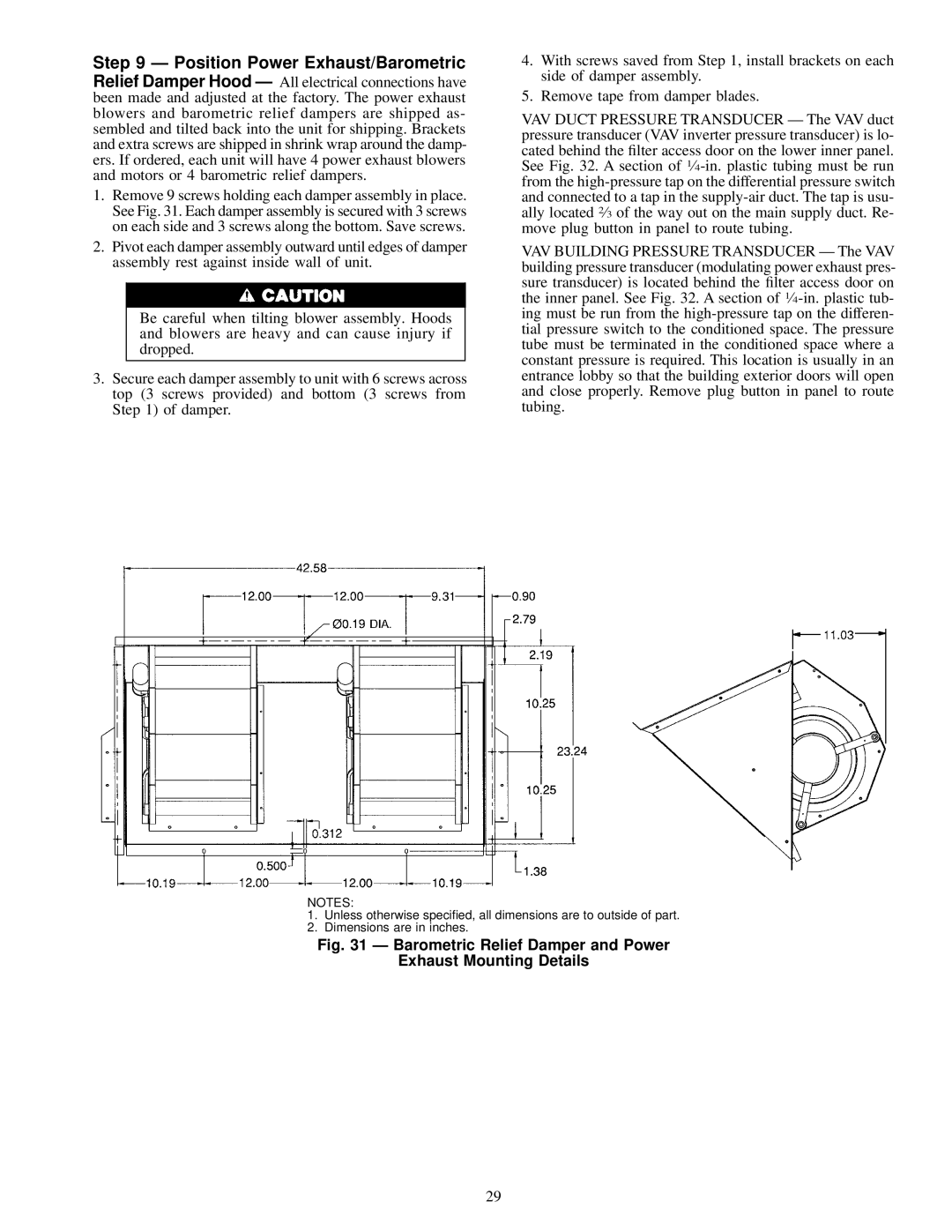
1.Remove 9 screws holding each damper assembly in place. See Fig. 31. Each damper assembly is secured with 3 screws on each side and 3 screws along the bottom. Save screws.
2.Pivot each damper assembly outward until edges of damper assembly rest against inside wall of unit.
Be careful when tilting blower assembly. Hoods and blowers are heavy and can cause injury if dropped.
3.Secure each damper assembly to unit with 6 screws across top (3 screws provided) and bottom (3 screws from Step 1) of damper.
4.With screws saved from Step 1, install brackets on each side of damper assembly.
5.Remove tape from damper blades.
VAV DUCT PRESSURE TRANSDUCER Ð The VAV duct pressure transducer (VAV inverter pressure transducer) is lo- cated behind the ®lter access door on the lower inner panel. See Fig. 32. A section of
VAV BUILDING PRESSURE TRANSDUCER Ð The VAV building pressure transducer (modulating power exhaust pres- sure transducer) is located behind the ®lter access door on the inner panel. See Fig. 32. A section of
NOTES:
1.Unless otherwise speci®ed, all dimensions are to outside of part.
2.Dimensions are in inches.
Fig. 31 Ð Barometric Relief Damper and Power
Exhaust Mounting Details
29