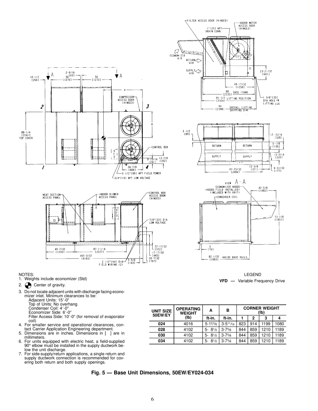
NOTES:
1.Weights include economizer (Std)
2.![]() Center of gravity.
Center of gravity.
3.Do not locate adjacent units with discharge facing econo- mizer inlet. Minimum clearances to be:
Adjacent Units: 15
Top of Units: No overhang
Condenser Coil: 4
Economizer Side: 6
Filter Access Side: 10
4.For smaller service and operational clearances, con- tact Carrier Application Engineering department.
5.Dimensions are in inches. Dimensions in [ ] are in millimeters.
6.For units equipped with electric heat, a
7.For
LEGEND
VFD Ð Variable Frequency Drive
UNIT SIZE | OPERATING | A | B | CORNER WEIGHT | ||||
WEIGHT |
|
| (lb) |
| ||||
50EW/EY |
|
|
|
|
| |||
(lb) |
| 1 | 2 |
| 3 | 4 | ||
|
| |||||||
024 | 4016 | 823 | 914 |
| 1199 | 1080 | ||
028 | 4102 | 5- 81¤2 | 844 | 859 |
| 1210 | 1189 | |
030 | 4102 | 5- 81¤2 | 844 | 859 |
| 1210 | 1189 | |
034 | 4102 | 5- 81¤2 | 844 | 859 |
| 1210 | 1189 | |
Fig. 5 Ð Base Unit Dimensions, 50EW/EY024-034
6