Minimum Damper Position Setting Ð Setting of the out- door air damper position is performed in conjunction with a shortened version of the
The
BLACK SEAL STRIP (CENTERED)
FILTER COVER
Fig. 27 Ð Attaching Seal Strip
to Filter Cover
HH57AC077
ENTHALPY CONTROL
C7400A1004 | HH57AC078 |
ENTHALPY SENSOR |
+ | (USED WITH ENTHALPY |
| CONTROL FOR DIFFERENTIAL |
| ENTHALPY OPERATION) |
Fig. 28 Ð Differential Enthalpy Control
and Sensor
position to go to 10% for 30 seconds, then 20% for 30 sec- onds, and when it reaches 30% close DIP switch no. 6 dur- ing the
The minimum outdoor air damper position is now set.
ECONOMIZER SETTINGS
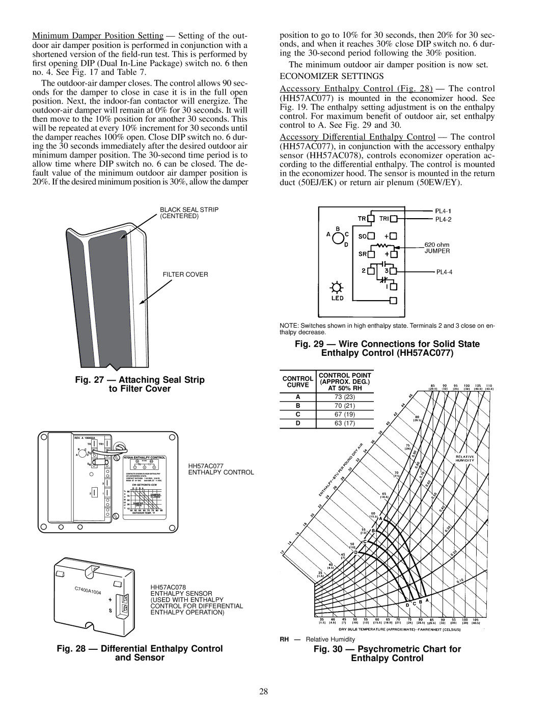
Accessory Enthalpy Control (Fig. 28) Ð The control (HH57AC077) is mounted in the economizer hood. See Fig. 19. The enthalpy setting adjustment is on the enthalpy control. For maximum bene®t of outdoor air, set enthalpy control to A. See Fig. 29 and 30.
Accessory Differential Enthalpy Control Ð The control (HH57AC077), in conjunction with the accessory enthalpy sensor (HH57AC078), controls economizer operation ac- cording to the differential enthalpy. The control is mounted in the economizer hood. The sensor is mounted in the return duct (50EJ/EK) or return air plenum (50EW/EY).
NOTE: Switches shown in high enthalpy state. Terminals 2 and 3 close on en- thalpy decrease.
Fig. 29 Ð Wire Connections for Solid State
Enthalpy Control (HH57AC077)
CONTROL | CONTROL POINT | |
CURVE | (APPROX. DEG.) | |
AT 50% RH | ||
|
A73 (23)
B70 (21)
C67 (19)
D63 (17)
RH Ð Relative Humidity
Fig. 30 Ð Psychrometric Chart for
Enthalpy Control
28