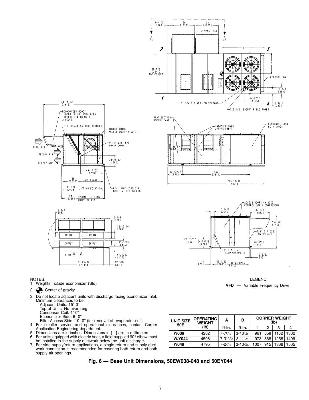
NOTES:
1.Weights include economizer (Std)
2.![]() Center of gravity.
Center of gravity.
3.Do not locate adjacent units with discharge facing economizer inlet. Minimum clearances to be:
Adjacent Units: 15
Top of Units: No overhang
Condenser Coil: 4
Economizer Side: 6
Filter Access Side: 10
4.For smaller service and operational clearances, contact Carrier Application Engineering department.
5. Dimensions are in inches. Dimensions in [ ] are in millimeters.
6.For units equipped with electric heat, a
7.For
LEGEND
VFD Ð Variable Frequency Drive
UNIT SIZE | OPERATING | A | B | CORNER WEIGHT | ||||
| (lb) |
| ||||||
50E | WEIGHT |
|
|
|
| |||
(lb) | 1 | 2 | 3 | 4 | ||||
| ||||||||
W038 | 4282 | 961 | 858 | 1162 | 1302 | |||
W/Y044 | 4508 | 973 | 868 | 1258 | 1409 | |||
W048 | 4795 | 1007 | 915 | 1368 | 1505 | |||
Fig. 6 Ð Base Unit Dimensions, 50EW038-048 and 50EY044
7