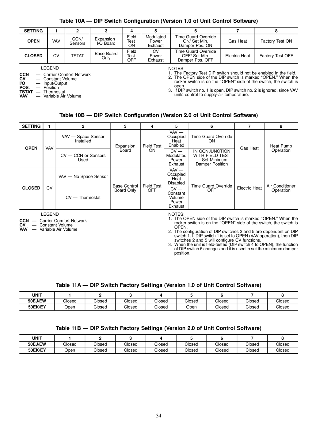
Table 10A Ð DIP Switch Con®guration (Version 1.0 of Unit Control Software)
SETTING | 1 | 2 | 3 | 4 | 5 | 6 | 7 | 8 | |
OPEN |
| CCN/ | Expansion | Field | Modulated | Time Guard Override |
|
| |
VAV | Test | Power | ON/ Set Min. | Gas Heat | Factory Test ON | ||||
Sensors | I/O Board | ||||||||
|
| ON | Exhaust | Damper Pos. ON |
|
| |||
|
|
|
|
|
| ||||
CLOSED |
|
| Base Board | Field | CV | Time Guard Override |
|
| |
CV | TSTAT | Test | Power | OFF/ Set Min. | Electric Heat | Factory Test OFF | |||
Only | |||||||||
|
|
| OFF | Exhaust | Damper Pos. OFF |
|
| ||
|
|
|
|
|
| ||||
|
|
|
|
|
|
|
|
|
|
| LEGEND |
CCN | Ð Carrier Comfort Network | |
CV | Ð Constant Volume | |
I/O | Ð | Input/Output |
POS. | Ð | Position |
TSTAT | Ð Thermostat | |
VAV | Ð Variable Air Volume | |
NOTES:
1.The Factory Test DIP switch should not be enabled in the ®eld.
2.The OPEN side of the DIP switch is marked ``OPEN.'' When the rocker switch is on the ``OPEN'' side of the switch, the switch is open.
3.If DIP switch no. 1 is open, DIP switch no. 2 is ignored, since VAV units control to
Table 10B Ð DIP Switch Con®guration (Version 2.0 of Unit Control Software)
SETTING | 1 | 2 | 3 | 4 | 5 | 6 | 7 | 8 |
|
|
|
|
| VAV Ð |
|
|
|
|
| VAV Ð Space Sensor |
|
| Occupied | Time Guard Override |
|
|
|
| Installed |
|
| Heat | ON |
|
|
OPEN | VAV |
| Expansion | Field Test | Enabled |
| Gas Heat | Heat Pump |
| Board | ON | CV Ð | IN CONJUNCTION | Operation | |||
|
|
|
| |||||
|
| CV Ð CCN or Sensors |
|
| Modulated | WITH FIELD TEST |
|
|
|
| Used |
|
| Power | Ð Set Minimum |
|
|
|
|
|
|
| Exhaust | Damper Position |
|
|
|
|
|
|
| VAV Ð |
|
|
|
|
| VAV Ð No Space Sensor |
|
| Occupied |
|
|
|
|
|
|
| Heat |
|
|
| |
|
|
|
|
|
|
|
| |
|
|
| Base Control | Field Test | Disabled | Time Guard Override |
| Air Conditioner |
CLOSED | CV |
| CV Ð | Electric Heat | ||||
| Board Only | OFF | OFF | Operation | ||||
|
|
| Constant |
| ||||
|
|
|
|
|
|
|
| |
|
| CV Ð Thermostat |
|
| Volume |
|
|
|
|
|
|
|
| Power |
|
|
|
|
|
|
|
| Exhaust |
|
|
|
LEGEND
CCN Ð Carrier Comfort Network
CV Ð Constant Volume
VAV Ð Variable Air Volume
NOTES:
1.The OPEN side of the DIP switch is marked ``OPEN.'' When the rocker switch is on the ``OPEN'' side of the switch, the switch is OPEN.
2.The con®guration of DIP switches 2 and 5 are dependent on DIP switch 1. If DIP switch 1 is set to OPEN (VAV operation), then DIP switches 2 and 5 will con®gure CV functions.
3.When the unit is
Table 11A Ð DIP Switch Factory Settings (Version 1.0 of Unit Control Software)
UNIT | 1 | 2 | 3 | 4 | 5 | 6 | 7 | 8 |
50EJ/EW | Closed | Closed | Closed | Closed | Closed | Closed | Closed | Closed |
50EK/EY | Open | Closed | Closed | Closed | Open | Closed | Closed | Closed |
|
|
|
|
|
|
|
|
|
Table 11B Ð DIP Switch Factory Settings (Version 2.0 of Unit Control Software)
UNIT | 1 | 2 | 3 | 4 | 5 | 6 | 7 | 8 |
50EJ/EW | Closed | Closed | Closed | Closed | Closed | Closed | Closed | Closed |
50EK/EY | Open | Closed | Closed | Closed | Closed | Closed | Closed | Closed |
34