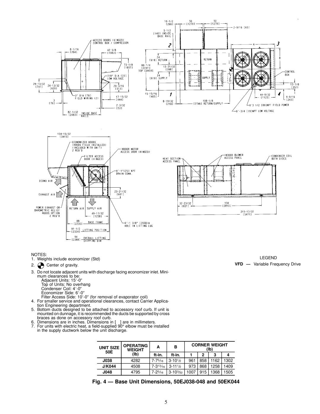
NOTES: | LEGEND | |
1. | Weights include economizer (Std) | |
2. | Center of gravity. | VFD Ð Variable Frequency Drive |
3.Do not locate adjacent units with discharge facing economizer inlet. Mini- mum clearances to be:
Adjacent Units: 15
Top of Units: No overhang
Condenser Coil: 4
Economizer Side: 6
Filter Access Side: 10
4.For smaller service and operational clearances, contact Carrier Applica- tion Engineering department.
5.Bottom ducts designed to be attached to accessory roof curb. If unit is
mounted on dunnage, it is recommended the ducts be supported by cross braces as done on accessory roof curb.
6. Dimensions are in inches. Dimensions in [ ] are in millimeters.
7.For units with electric heat, a
UNIT SIZE | OPERATING | A | B | CORNER WEIGHT | ||||
WEIGHT |
| (lb) |
| |||||
50E |
|
|
|
| ||||
(lb) | 1 | 2 | 3 | 4 | ||||
| ||||||||
J038 | 4282 | 961 | 858 | 1162 | 1302 | |||
J/K044 | 4508 | 973 | 868 | 1258 | 1409 | |||
J048 | 4795 | 1007 | 915 | 1368 | 1505 | |||
Fig. 4 Ð Base Unit Dimensions, 50EJ038-048 and 50EK044
5