Table 2 Ð Evaporator Fan Motor Data
|
| MOTOR | FAN |
| MOTOR |
|
| FAN |
|
|
| BELT | |
|
|
| SHEAVE | BUSHING |
| SHEAVE | BUSHING |
| OUTSIDE | ||||
UNIT | MOTOR | SHAFT | SHAFT | MOTOR | FAN |
| TENSION | ||||||
PITCH | DIAMETER | PITCH | DIAMETER | BELT | BELT | ||||||||
SIZE | HP | DIAMETER | SPEED | SHEAVE | SHEAVE | (Lb @ | |||||||
DIAMETER | (in.) | DIAMETER | (in.) |
| LENGTH | ||||||||
|
| (in.) | (rpm) |
|
|
| .24 in.) | ||||||
|
|
| (in.) |
|
| (in.) |
|
|
| ||||
|
|
|
|
|
|
|
|
|
|
| |||
024 | 5 | 1.12 | 725 | BK52 | 4.6 | 1B5V110 | 11.1 | BX59 | 62 | 5.02 | |||
10 | 1.38 | 924 | BK72 | 6.6 | 1B5V124 | 12.5 | BX60 | 63 | 7.05 | ||||
| 15 | 1.62 | 1088 | 1B5V68 | 6.9 | 1B5V110 | 11.1 | 5VX590 | 59 | 9.38 | |||
028 | 7.5 | 1.38 | 773 | BK55H | 4.9 | 1B5V110 | 11.1 | BX56 | 59 | 6.87 | |||
10 | 1.38 | 962 | BK67H | 6.1 | 1B5V110 | 11.1 | BX56 | 59 | 7.26 | ||||
| 15 | 1.62 | 1119 | 1B5V70 | 7.1 | 1B5V110 | 11.1 | 5VX590 | 59 | 9.17 | |||
030 | 10 | 1.38 | 843 | BK72 | 6.6 | 1B5V136 | 13.7 | BX62 | 65 | 6.96 | |||
15 | 1.62 | 1056 | 1B5V66 | 6.7 | 1B5V110 | 11.1 | 5VX590 | 59 | 9.60 | ||||
| 20 | 1.62 | 1182 | 1B5V74 | 7.5 | 1B5V110 | 11.1 | 5VX600 | 60 | 11.67 | |||
034 | 10 | 1.38 | 896 | BK70H | 6.4 | 1B5V124 | 12.5 | BX60 | 63 | 7.20 | |||
15 | 1.62 | 1088 | 1B5V68 | 6.9 | 1B5V110 | 11.1 | 5VX590 | 59 | 9.38 | ||||
| 20 | 1.62 | 1182 | 1B5V74 | 7.5 | 1B5V110 | 11.1 | 5VX600 | 60 | 11.17 | |||
038 | 10 | 1.38 | 788 | 2BK47 | 4.1 | 2B5V90 | 9.1 | BX51 | 54 | 5.49 | |||
15 | 1.62 | 966 | 1B5V68 | 6.9 | 1B5V124 | 12.5 | 5VX630 | 63 | 9.22 | ||||
| 20 | 1.62 | 1050 | 1B5V74 | 7.5 | 1B5V124 | 12.5 | 5VX650 | 65 | 10.02 | |||
044 | 15 | 1.62 | 966 | 1B5V68 | 6.9 | 1B5V124 | 12.5 | 5VX630 | 63 | 9.54 | |||
20 | 1.62 | 1035 | 1B5V80 | 8.1 | 1B5V136 | 13.7 | 5VX670 | 67 | 10.37 | ||||
| 25 | 1.88 | 1162 | 1B5V90 | 9.1 | 1B5V136 | 13.7 | 5VX680 | 68 | 10.88 | |||
048 | 20 | 1.62 | 1019 | 2B5V52 | 5.3 | 2B5V90 | 9.1 | 5VX550 | 55 | 7.93 | |||
25 | 1.88 | 1135 | 2B5V58 | 5.9 | 2B5V90 | 9.1 | 5VX560 | 56 | 8.66 | ||||
| 30 | 1.88 | 1182 | 2B5V76 | 7.5 | 2B5V110 | 11.1 | 5VX610 | 59 | 9.07 |
NOTE: Motor shaft speed is 1750 rpm. The fan shaft diameter is 111¤16 inches.
ROOF MOUNT Ð Check building codes for weight distri- bution requirements.
Step 3 Ð Field Fabricate Ductwork Ð Secure all ducts to building structure. Use ¯exible duct connectors be- tween unit and ducts as required. Insulate and weatherproof all external ductwork, joints, and roof openings with counter ¯ashing and mastic in accordance with applicable codes.
Ducts passing through an unconditioned space must be insulated and covered with a vapor barrier.
To attach ductwork to roof curb, insert ductwork approxi- mately 10 to 11 in. up into the curb. Connect ductwork to
The units with electric heat require a
NOTE: A
Outlet grilles must not lie directly below unit discharge.
Step 4 Ð Make Unit Duct Connections
50EJ,EK UNITS Ð Unit is shipped for
50EW,EY UNITS Ð Remove shipping covers from supply and return air openings. Attach
Install accessory barometric relief or power exhaust in the
Step 5 Ð Trap Condensate Drain Ð See Fig.
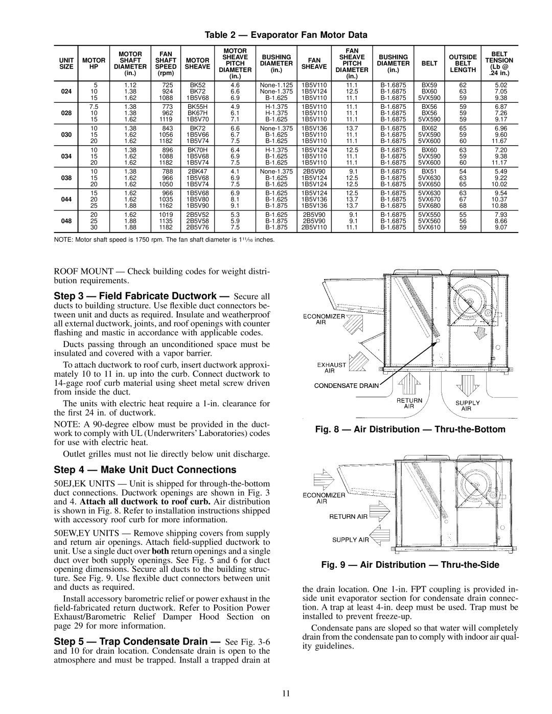
Fig. 8 Ð Air Distribution Ð Thru-the-Bottom
Fig. 9 Ð Air Distribution Ð Thru-the-Side
the drain location. One
Condensate pans are sloped so that water will completely drain from the condensate pan to comply with indoor air qual- ity guidelines.
11