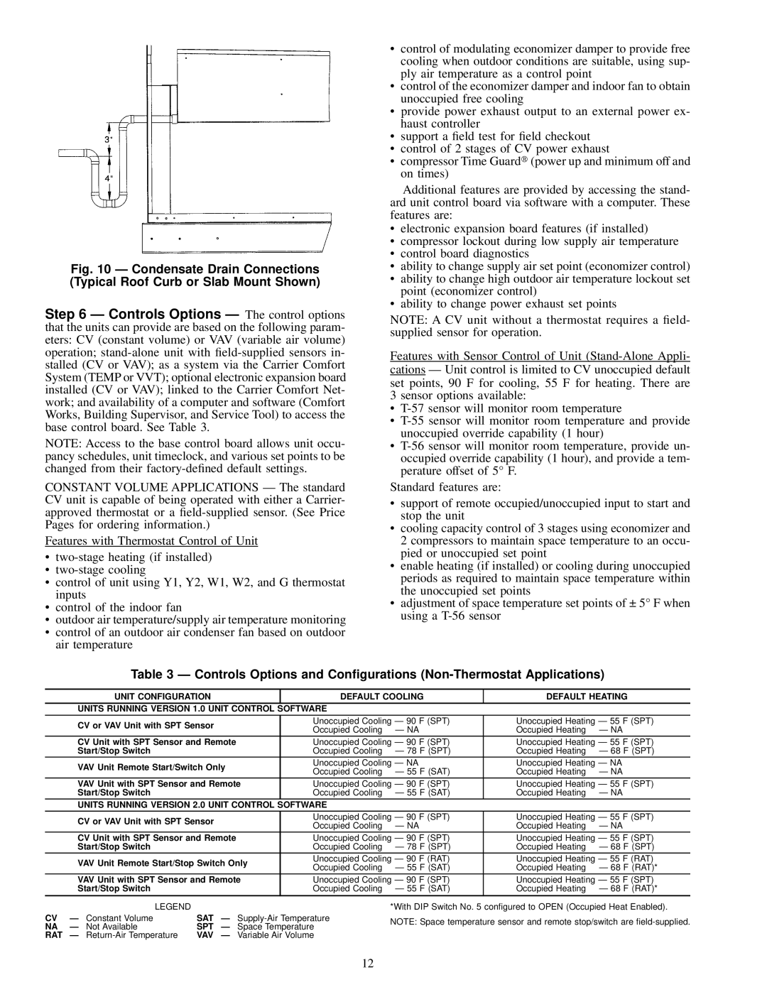
Fig. 10 Ð Condensate Drain Connections (Typical Roof Curb or Slab Mount Shown)
Step 6 Ð Controls Options Ð The control options that the units can provide are based on the following param- eters: CV (constant volume) or VAV (variable air volume) operation;
NOTE: Access to the base control board allows unit occu- pancy schedules, unit timeclock, and various set points to be changed from their
CONSTANT VOLUME APPLICATIONS Ð The standard CV unit is capable of being operated with either a Carrier- approved thermostat or a
Features with Thermostat Control of Unit
·
·
·control of unit using Y1, Y2, W1, W2, and G thermostat inputs
·control of the indoor fan
·outdoor air temperature/supply air temperature monitoring
·control of an outdoor air condenser fan based on outdoor air temperature
·control of modulating economizer damper to provide free cooling when outdoor conditions are suitable, using sup- ply air temperature as a control point
·control of the economizer damper and indoor fan to obtain unoccupied free cooling
·provide power exhaust output to an external power ex- haust controller
·support a ®eld test for ®eld checkout
·control of 2 stages of CV power exhaust
· compressor Time Guard (power up and minimum off and on times)
Additional features are provided by accessing the stand- ard unit control board via software with a computer. These features are:
·electronic expansion board features (if installed)
·compressor lockout during low supply air temperature
·control board diagnostics
·ability to change supply air set point (economizer control)
·ability to change high outdoor air temperature lockout set point (economizer control)
·ability to change power exhaust set points
NOTE: A CV unit without a thermostat requires a ®eld- supplied sensor for operation.
Features with Sensor Control of Unit
3 sensor options available:
·
·
·
Standard features are:
·support of remote occupied/unoccupied input to start and stop the unit
·cooling capacity control of 3 stages using economizer and 2 compressors to maintain space temperature to an occu- pied or unoccupied set point
·enable heating (if installed) or cooling during unoccupied periods as required to maintain space temperature within the unoccupied set points
·adjustment of space temperature set points of ± 5° F when using a
Table 3 Ð Controls Options and Con®gurations
UNIT CONFIGURATION | DEFAULT COOLING | DEFAULT HEATING | |||
UNITS RUNNING VERSION 1.0 UNIT CONTROL SOFTWARE |
|
|
| ||
CV or VAV Unit with SPT Sensor | Unoccupied Cooling Ð 90 F (SPT) | Unoccupied Heating Ð 55 F (SPT) | |||
Occupied Cooling | Ð NA | Occupied Heating | Ð NA | ||
| |||||
CV Unit with SPT Sensor and Remote | Unoccupied Cooling Ð 90 F (SPT) | Unoccupied Heating Ð 55 F (SPT) | |||
Start/Stop Switch | Occupied Cooling | Ð 78 F (SPT) | Occupied Heating | Ð 68 F (SPT) | |
VAV Unit Remote Start/Switch Only | Unoccupied Cooling Ð NA | Unoccupied Heating Ð NA | |||
Occupied Cooling | Ð 55 F (SAT) | Occupied Heating | Ð NA | ||
| |||||
VAV Unit with SPT Sensor and Remote | Unoccupied Cooling Ð 90 F (SPT) | Unoccupied Heating Ð 55 F (SPT) | |||
Start/Stop Switch | Occupied Cooling | Ð 55 F (SAT) | Occupied Heating | Ð NA | |
UNITS RUNNING VERSION 2.0 UNIT CONTROL SOFTWARE |
|
|
| ||
CV or VAV Unit with SPT Sensor | Unoccupied Cooling Ð 90 F (SPT) | Unoccupied Heating Ð 55 F (SPT) | |||
Occupied Cooling | Ð NA | Occupied Heating | Ð NA | ||
| |||||
CV Unit with SPT Sensor and Remote | Unoccupied Cooling Ð 90 F (SPT) | Unoccupied Heating Ð 55 F (SPT) | |||
Start/Stop Switch | Occupied Cooling | Ð 78 F (SPT) | Occupied Heating | Ð 68 F (SPT) | |
VAV Unit Remote Start/Stop Switch Only | Unoccupied Cooling Ð 90 F (RAT) | Unoccupied Heating Ð 55 F (RAT) | |||
Occupied Cooling | Ð 55 F (SAT) | Occupied Heating | Ð 68 F (RAT)* | ||
| |||||
VAV Unit with SPT Sensor and Remote | Unoccupied Cooling Ð 90 F (SPT) | Unoccupied Heating Ð 55 F (SPT) | |||
Start/Stop Switch | Occupied Cooling | Ð 55 F (SAT) | Occupied Heating | Ð 68 F (RAT)* | |
|
| LEGEND |
|
|
| *With DIP Switch No. 5 con®gured to OPEN (Occupied Heat Enabled). | |
CV | Ð | Constant Volume | SAT | Ð | NOTE: Space temperature sensor and remote stop/switch are | ||
NA | Ð | Not Available | SPT | Ð | Space Temperature | ||
| |||||||
RAT | Ð | VAV | Ð | Variable Air Volume |
|
12