Operation
High Altitude Operation
Because the air is less dense at higher altitudes, there is a possibility of nuisance arcing in the Electronic Air Cleaner. The homeowner can quickly and easily correct this condition.
1.Make sure the HVAC System Blower is not operating, the ON/OFF switch is in OFF position and the circuit breaker is turned OFF or input power cord is disconnected.
2.Remove the Front Panel Assembly.
3.Remove the cover from the Power Tray Assembly by removing the two screws on top of unit. (The entire Power Tray Assembly may be removed from the cabinet by removing two screws from inside the cabinet.)
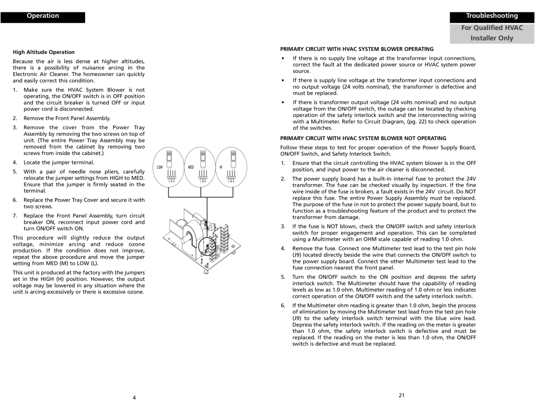
4.Locate the jumper terminal.
5.With a pair of needle nose pliers, carefully relocate the jumper settings from HIGH to MED. Ensure that the jumper is firmly seated in the terminal.
6.Replace the Power Tray Cover and secure it with two screws.
7.Replace the Front Panel Assembly, turn circuit breaker ON, reconnect input power cord and turn ON/OFF switch ON.
This procedure will slightly reduce the output voltage, minimize arcing and reduce ozone production. If the condition does not improve, repeat the above procedure and move the jumper setting from MED (M) to LOW (L).
This unit is produced at the factory with the jumpers set in the HIGH (H) position. However, the output voltage may be lowered in any situation where the unit is arcing excessively or there is excessive ozone.
Troubleshooting
For Qualified HVAC
Installer Only
PRIMARY CIRCUIT WITH HVAC SYSTEM BLOWER OPERATING
•If there is no supply line voltage at the transformer input connections, correct the fault at the dedicated power source or HVAC system power source.
•If there is supply line voltage at the transformer input connections and no output voltage (24 volts nominal), the transformer is defective and must be replaced.
•If there is transformer output voltage (24 volts nominal) and no output voltage from the ON/OFF switch, the outage can be located by checking operation of the safety interlock switch and the interconnecting wiring with a Multimeter. Refer to Circuit Diagram, (pg. 22) to check operation of the switches.
PRIMARY CIRCUIT WITH HVAC SYSTEM BLOWER NOT OPERATING
Follow these steps to test for proper operation of the Power Supply Board, ON/OFF Switch, and Safety Interlock Switch.
1.Ensure that the circuit controlling the HVAC system blower is in the OFF position, and input power to the air cleaner is disconnected.
2.The power supply board has a
3.If the fuse is NOT blown, check the ON/OFF switch and safety interlock switch for proper engagement and operation. This can be completed using a Multimeter with an OHM scale capable of reading 1.0 ohm.
4.Remove the fuse. Connect one Multimeter test lead to the test pin hole (J9) located directly beside the wire that connects the ON/OFF switch to the power supply board. Connect the other Multimeter test lead to the fuse connection nearest the front panel.
5.Turn the ON/OFF switch to the ON position and depress the safety interlock switch. The Multimeter should have the capability of reading levels as low as 1.0 ohm. Multimeter reading of 1.0 ohm or less indicates correct operation of the ON/OFF switch and the safety interlock switch.
6.If the Multimeter ohm reading is greater than 1.0 ohm, begin the process of elimination by moving the Multimeter test lead from the test pin hole (J9) to the safety interlock switch terminal with the blue wire lead. Depress the safety interlock switch. If the reading on the meter is greater than 1.0 ohm, the safety interlock switch is defective and must be replaced. If the reading on the meter is less than 1.0 ohm, the ON/OFF switch is defective and must be replaced.
4 | 21 |
|