Basic Operation continued
Indicator Lights
All Indicator Light descriptions apply when the UPS is plugged into an AC outlet and turned on.
LINE POWER: This green light will turn ON whenever your UPS is receiving normal AC line power. It will flash while the UPS is in CHARGE ONLY mode to indicate that the UPS will not provide battery backup during a black- out or brownout.
BATTERY POWER: This yellow light will turn ON when your UPS is pro- viding your equipment with battery power.
BATTERY CHARGE: This red light will turn ON continuously after the UPS runs a
OVERLOAD (Select models only): This red light will turn ON continuously when the UPS is providing power from battery or after the UPS runs a
VOLTAGE REGULATION (Select models only): This light will turn ON when your UPS is automatically correcting high or low utility line voltage. The UPS will also click gently when this automatic voltage regu- lation is operating. These are both normal functions of your UPS, and no action is required on your part.
Other UPS Features
AC Receptacles: “UPS/Surge” receptacles are used to provide your con- nected equipment with AC line power during normal operation and battery power during blackouts and brownouts. They also protect your equipment against damaging surges and line noise.
Telephone/Network Protection Jacks (Select models only): These jacks protect your equipment against surges over a telephone or data line. Your UPS has either jacks which can be used with both phone and data lines, or jacks which can be used with phone lines only. See Specifications to deter- mine what kind of jacks your UPS has. Connecting your equipment to these jacks is optional. Your UPS will work properly without this connection.
6
Basic Operation continued
USB Port: The USB port connects your UPS to any USB workstation or server. Using this port, your UPS can communicate
Battery Replacement Door: Under normal conditions, the original bat- tery in your UPS will last several years. Battery replacement should be performed only by qualified service personnel. Refer to “Battery Warnings” in the Safety section on page 2.
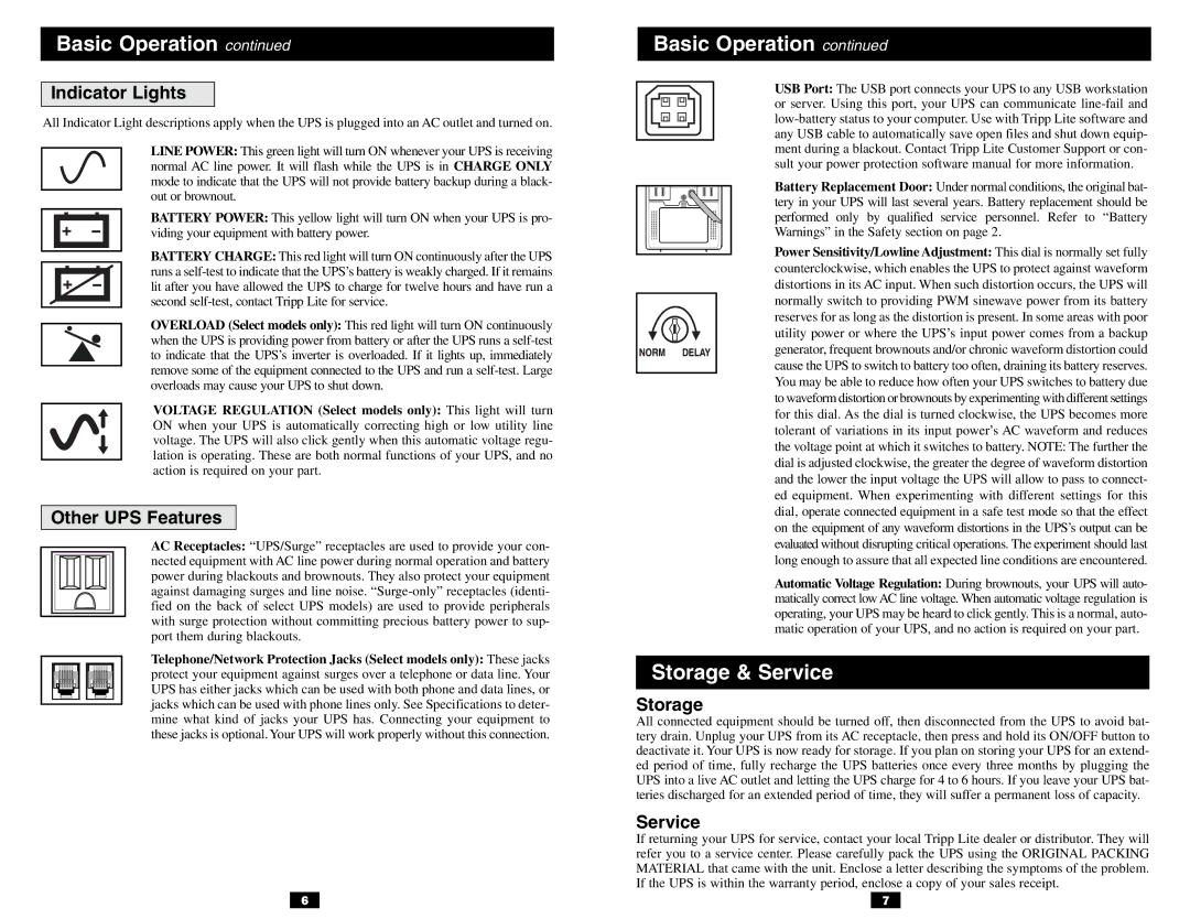
Power Sensitivity/Lowline Adjustment: This dial is normally set fully counterclockwise, which enables the UPS to protect against waveform distortions in its AC input. When such distortion occurs, the UPS will normally switch to providing PWM sinewave power from its battery reserves for as long as the distortion is present. In some areas with poor utility power or where the UPS’s input power comes from a backup generator, frequent brownouts and/or chronic waveform distortion could cause the UPS to switch to battery too often, draining its battery reserves. You may be able to reduce how often your UPS switches to battery due to waveform distortion or brownouts by experimenting with different settings for this dial. As the dial is turned clockwise, the UPS becomes more tolerant of variations in its input power’s AC waveform and reduces the voltage point at which it switches to battery. NOTE: The further the dial is adjusted clockwise, the greater the degree of waveform distortion and the lower the input voltage the UPS will allow to pass to connect- ed equipment. When experimenting with different settings for this dial, operate connected equipment in a safe test mode so that the effect on the equipment of any waveform distortions in the UPS’s output can be evaluated without disrupting critical operations. The experiment should last long enough to assure that all expected line conditions are encountered.
Automatic Voltage Regulation: During brownouts, your UPS will auto- matically correct low AC line voltage. When automatic voltage regulation is operating, your UPS may be heard to click gently. This is a normal, auto- matic operation of your UPS, and no action is required on your part.
Storage & Service
Storage
All connected equipment should be turned off, then disconnected from the UPS to avoid bat- tery drain. Unplug your UPS from its AC receptacle, then press and hold its ON/OFF button to deactivate it. Your UPS is now ready for storage. If you plan on storing your UPS for an extend- ed period of time, fully recharge the UPS batteries once every three months by plugging the UPS into a live AC outlet and letting the UPS charge for 4 to 6 hours. If you leave your UPS bat- teries discharged for an extended period of time, they will suffer a permanent loss of capacity.
Service
If returning your UPS for service, contact your local Tripp Lite dealer or distributor. They will refer you to a service center. Please carefully pack the UPS using the ORIGINAL PACKING MATERIAL that came with the unit. Enclose a letter describing the symptoms of the problem. If the UPS is within the warranty period, enclose a copy of your sales receipt.
7