and run the self-test again. If the batteries seem weak, the “  ” LED will stay lit and the UPS will continue to beep after the test; if this happens, let UPS charge its batteries for 12 hours and repeat the test. If the condition persists, contact Tripp Lite for service. CAUTION: Do not unplug your UPS to test its batteries. This will remove safe electrical grounding and may introduce a damaging surge into your network connections.
Indicator Lights
All Indicator Light descriptions apply when the UPS is plugged into an AC outlet and turned on.
LINE POWER: This green light will turn ON whenever your UPS is receiving normal AC line power. It will flash while the UPS is in CHARGE ONLY mode to indicate that the UPS will not provide battery backup during a blackout or brownout.
BATTERY POWER: This light indicates battery charge level: Green means the batteries are fully charged or nearly so, yellow means the batteries are partially charged, and red means the batteries are nearly depleted.
VOLTAGE REGULATION: This light will turn ON when your UPS is automatically correcting high or low utility line voltage. The UPS will also click gently when this automatic voltage regulation is operating. These are both normal functions of your UPS, and no action is required on your part.
BATTERY CHARGE: This red light will turn ON continuously after the UPS runs a self-test to indicate that the UPS’s battery is weakly charged. If it remains lit after you have allowed the UPS to charge for twelve hours and have run a second self-test, contact Tripp Lite for service.
OVERLOAD: This light shows how heavy is the load on the UPS’s inverter. Green indicates a light load, yellow indicates a medium load, and red indicates a heavy load (above 85% of the UPS’s output capacity). If this light is flashing, the UPS is overloaded and will not be able to provide power to connected equipment during a power outage. Unplug equipment from the UPS until this LED stops flashing.
Other UPS Features
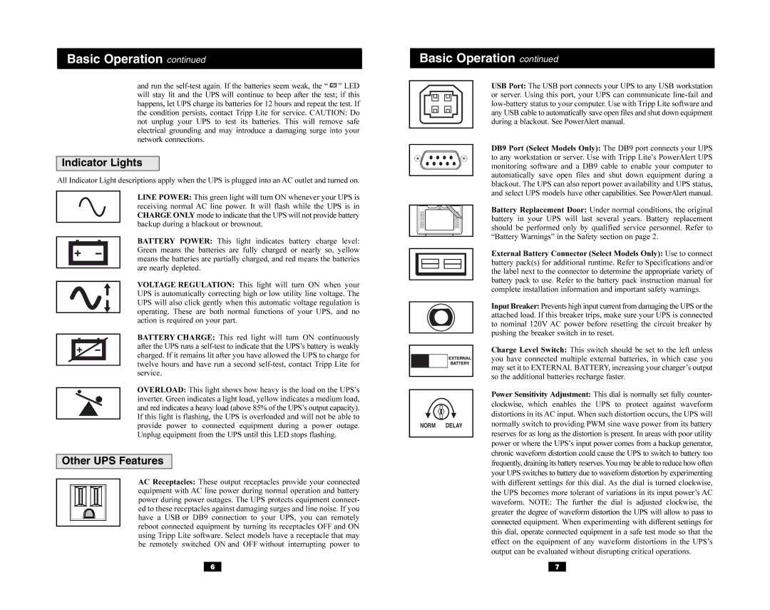
AC Receptacles: These output receptacles provide your connected equipment with AC line power during normal operation and battery power during power outages. The UPS protects equipment connect- ed to these receptacles against damaging surges and line noise. If you have a USB or DB9 connection to your UPS, you can remotely reboot connected equipment by turning its receptacles OFF and ON using Tripp Lite software. Select models have a receptacle that may be remotely switched ON and OFF without interrupting power to
USB Port: The USB port connects your UPS to any USB workstation or server. Using this port, your UPS can communicate line-fail and low-battery status to your computer. Use with Tripp Lite software and any USB cable to automatically save open files and shut down equipment during a blackout. See PowerAlert manual.
DB9 Port (Select Models Only): The DB9 port connects your UPS to any workstation or server. Use with Tripp Lite’s PowerAlert UPS monitoring software and a DB9 cable to enable your computer to automatically save open files and shut down equipment during a blackout. The UPS can also report power availability and UPS status, and select UPS models have other capabilities. See PowerAlert manual.
Battery Replacement Door: Under normal conditions, the original battery in your UPS will last several years. Battery replacement should be performed only by qualified service personnel. Refer to “Battery Warnings” in the Safety section on page 2.
External Battery Connector (Select Models Only): Use to connect battery pack(s) for additional runtime. Refer to Specifications and/or the label next to the connector to determine the appropriate variety of battery pack to use. Refer to the battery pack instruction manual for complete installation information and important safety warnings.
Input Breaker: Prevents high input current from damaging the UPS or the attached load. If this breaker trips, make sure your UPS is connected to nominal 120V AC power before resetting the circuit breaker by pushing the breaker switch in to reset.
Charge Level Switch: This switch should be set to the left unless you have connected multiple external batteries, in which case you may set it to EXTERNAL BATTERY, increasing your charger’s output so the additional batteries recharge faster.
Power Sensitivity Adjustment: This dial is normally set fully counter- clockwise, which enables the UPS to protect against waveform distortions in its AC input. When such distortion occurs, the UPS will normally switch to providing PWM sine wave power from its battery reserves for as long as the distortion is present. In areas with poor utility power or where the UPS’s input power comes from a backup generator, chronic waveform distortion could cause the UPS to switch to battery too frequently, draining its battery reserves.You may be able to reduce how often your UPS switches to battery due to waveform distortion by experimenting with different settings for this dial. As the dial is turned clockwise, the UPS becomes more tolerant of variations in its input power’s AC waveform. NOTE: The further the dial is adjusted clockwise, the greater the degree of waveform distortion the UPS will allow to pass to connected equipment. When experimenting with different settings for this dial, operate connected equipment in a safe test mode so that the effect on the equipment of any waveform distortions in the UPS’s output can be evaluated without disrupting critical operations.