Feature Identification
Identify the premium features on your specific model and quickly locate instructions on how to maximize their use.
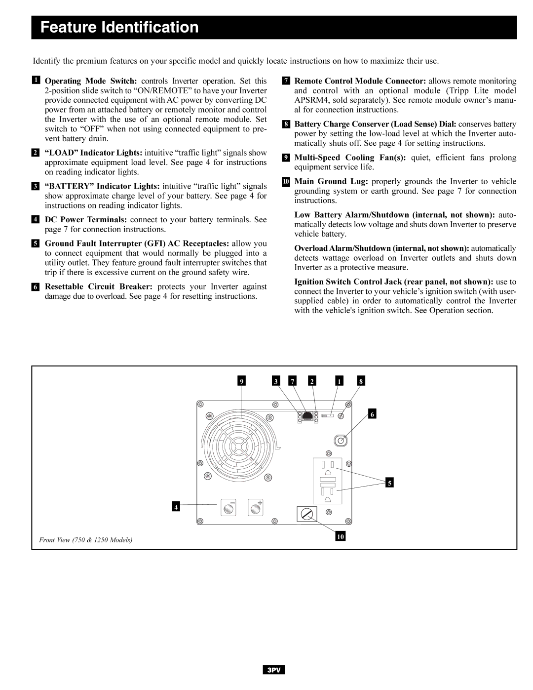
1Operating Mode Switch: controls Inverter operation. Set this
2“LOAD” Indicator Lights: intuitive “traffic light” signals show approximate equipment load level. See page 4 for instructions on reading indicator lights.
3“BATTERY” Indicator Lights: intuitive “traffic light” signals show approximate charge level of your battery. See page 4 for instructions on reading indicator lights.
4DC Power Terminals: connect to your battery terminals. See page 7 for connection instructions.
5Ground Fault Interrupter (GFI) AC Receptacles: allow you to connect equipment that would normally be plugged into a utility outlet. They feature ground fault interrupter switches that trip if there is excessive current on the ground safety wire.
6Resettable Circuit Breaker: protects your Inverter against damage due to overload. See page 4 for resetting instructions.
7Remote Control Module Connector: allows remote monitoring and control with an optional module (Tripp Lite model APSRM4, sold separately). See remote module owner’s manu- al for connection instructions.
8Battery Charge Conserver (Load Sense) Dial: conserves battery power by setting the
9
10Main Ground Lug: properly grounds the Inverter to vehicle grounding system or earth ground. See page 7 for connection instructions.
Low Battery Alarm/Shutdown (internal, not shown): auto- matically detects low voltage and shuts down Inverter to preserve vehicle battery.
Overload Alarm/Shutdown (internal, not shown): automatically detects wattage overload on Inverter outlets and shuts down Inverter as a protective measure.
Ignition Switch Control Jack (rear panel, not shown): use to connect the Inverter to your vehicle’s ignition switch (with user- supplied cable) in order to automatically control the Inverter with the vehicle's ignition switch. See Operation section.
9 |
| 3 |
| 7 |
| 2 |
| 1 |
| 8 |
6
![]()
![]() 5
5
| 4 |
Front View (750 & 1250 Models) | 10 |
|
3PV