Optional Installation
Tel/Modem, Ethernet and Coaxial Connections
Connect Your Equipment to the Power Conditioning Center's Tel/Modem Jacks: Connect a phone cable from the wall jack directly to the Power Conditioning Center's
Connect Your Equipment to the Surge Suppressor's Network Jacks:* Connect a data cord from the wall jack or cable/DSL modem directly to the Power Conditioning Center's network jack labeled “IN.” Connect a data cord from the Power Conditioning Center's network jack labeled “OUT” directly to the device to be protected. The Power Conditioning Center must always be the first item connected in line from the Ethernet source (typically a wall jack). The Power Conditioning Center must be plugged into a
* 10/100 BaseT/TX, Token Ring. Not compatible with PoE (Power Over Ethernet) applications
Connect Your Equipment to the Power Conditioning Center's Coaxial Jacks: Connect a coaxial cable from the wall jack directly to the Power Conditioning Center's “F” style coaxial jack labeled “IN.” Connect a coaxial cable from the Power Conditioning Center's “F” style coaxial jack labeled “OUT” directly to the device to be connected. Additional sets of coaxial jacks allow for simultaneous connection and protection of additional devices on additional lines (cable, antenna or satellite). Make sure that each device and its corresponding wall jack are connected to corresponding “IN” and “OUT” jacks on the Power Conditioning Center. The Power Conditioning Center must always be the first item connected in line from the coaxial wall jack. The Power Conditioning Center must be plugged into a
IR Outlet Control
Manual Control
Turn Controllable IR Outlets ON or OFF
•STEP 1: Momentarily press the “SELECT” Switch to choose which IR outlet you wish to select. The corresponding “OUTLET SELECT” LED will flash to indicate which outlet you have selected. Each time you press the switch, it will select the next LED in line.
•STEP 2: To turn IR outlet ON: When an outlet is selected using the “SELECT” Switch, momentarily press the "ENTER" Switch to turn the outlet ON. The corresponding “POWER ON” LED will illuminate to indicate power is ON at the outlet. The corresponding “OUTLET SELECT” LED will illuminate continuously to indicate the outlet is no longer selected. To turn IR outlet OFF: Momentarily press the “SELECT” Switch to choose which IR outlet you wish to turn off. The corresponding “OUTLET SELECT” LED will flash to indicate which outlet you have selected. Momentarily press the “ENTER” Switch to turn the outlet OFF. The corresponding “POWER ON” LED will go off to indicate power is OFF at the outlet. The corresponding “OUTLET SELECT” LED will also go off.
Set Delay Interval for Remote IR Outlet Power ON or Power OFF
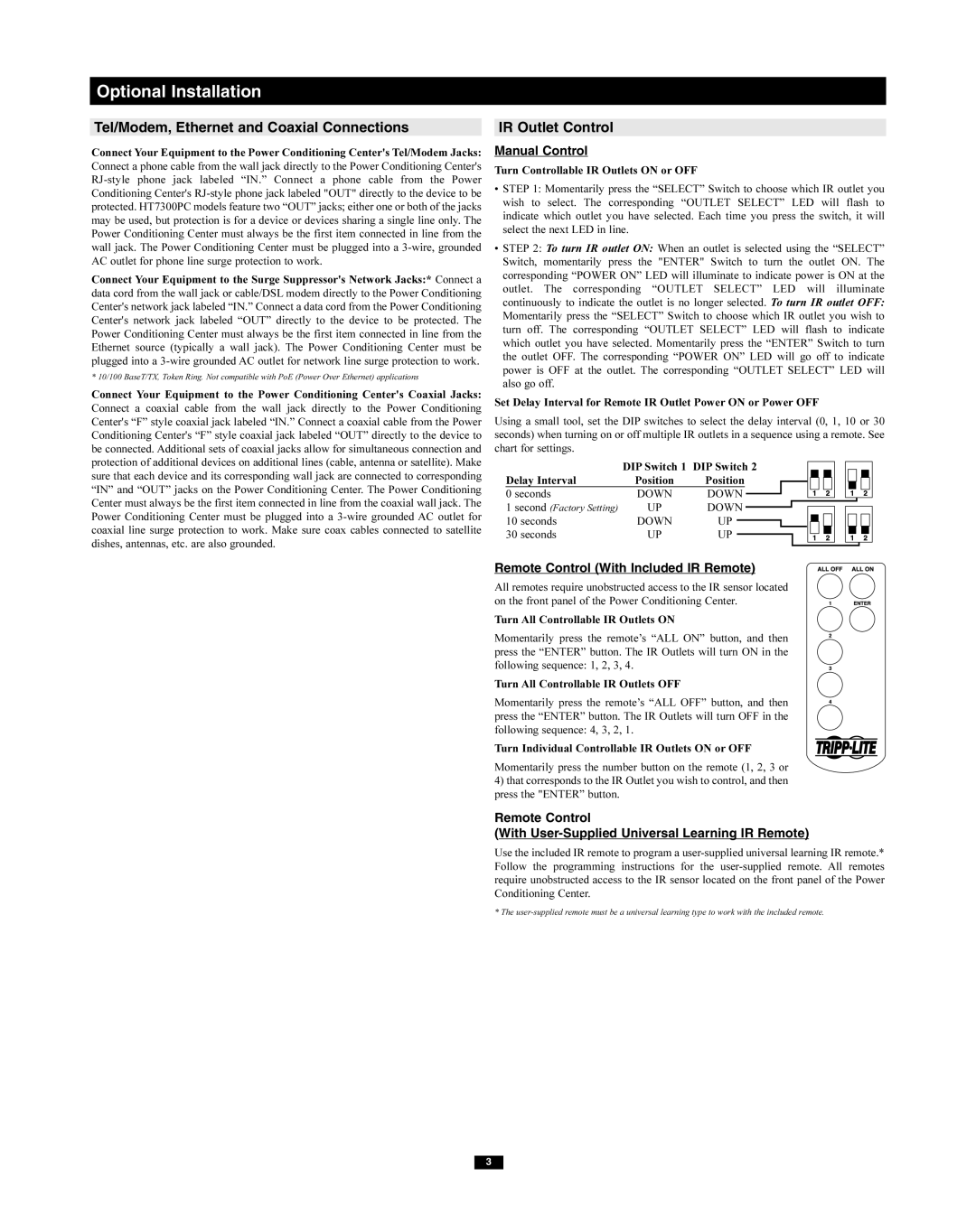
Using a small tool, set the DIP switches to select the delay interval (0, 1, 10 or 30 seconds) when turning on or off multiple IR outlets in a sequence using a remote. See chart for settings.
| DIP Switch 1 | DIP Switch 2 |
|
|
|
|
|
|
|
|
|
|
|
|
|
| ||||
|
|
|
|
|
|
|
|
|
|
|
|
|
|
| ||||||
Delay Interval | Position | Position |
|
|
|
|
|
|
|
|
|
|
|
|
|
|
| |||
0 seconds | DOWN | DOWN |
|
|
|
|
|
|
|
|
|
|
|
|
|
|
| |||
|
|
|
|
|
|
|
|
|
|
|
|
|
|
| ||||||
1 second (Factory Setting) | UP | DOWN |
|
|
|
|
|
|
|
|
|
|
|
|
|
|
|
| ||
|
|
|
|
|
|
|
|
|
|
|
|
|
|
| ||||||
10 seconds | DOWN | UP |
|
|
|
|
|
|
|
|
|
|
|
|
|
|
|
|
|
|
30 seconds | UP | UP |
|
|
|
|
|
|
|
|
|
|
|
|
|
|
| |||
|
|
|
|
|
|
|
|
|
|
|
|
|
|
| ||||||
|
|
|
|
|
|
|
|
|
|
|
|
|
|
|
|
|
|
|
|
|
|
|
|
|
|
|
|
|
|
|
|
|
|
|
|
|
|
|
|
|
|
Remote Control (With Included IR Remote)
All remotes require unobstructed access to the IR sensor located on the front panel of the Power Conditioning Center.
Turn All Controllable IR Outlets ON
Momentarily press the remote’s “ALL ON” button, and then press the “ENTER” button. The IR Outlets will turn ON in the following sequence: 1, 2, 3, 4.
Turn All Controllable IR Outlets OFF
Momentarily press the remote’s “ALL OFF” button, and then press the “ENTER” button. The IR Outlets will turn OFF in the following sequence: 4, 3, 2, 1.
Turn Individual Controllable IR Outlets ON or OFF
Momentarily press the number button on the remote (1, 2, 3 or
4)that corresponds to the IR Outlet you wish to control, and then press the "ENTER” button.
Remote Control
(With
Use the included IR remote to program a
* The
3