Features continued
P
Q
S
T
W
R
R
U V X
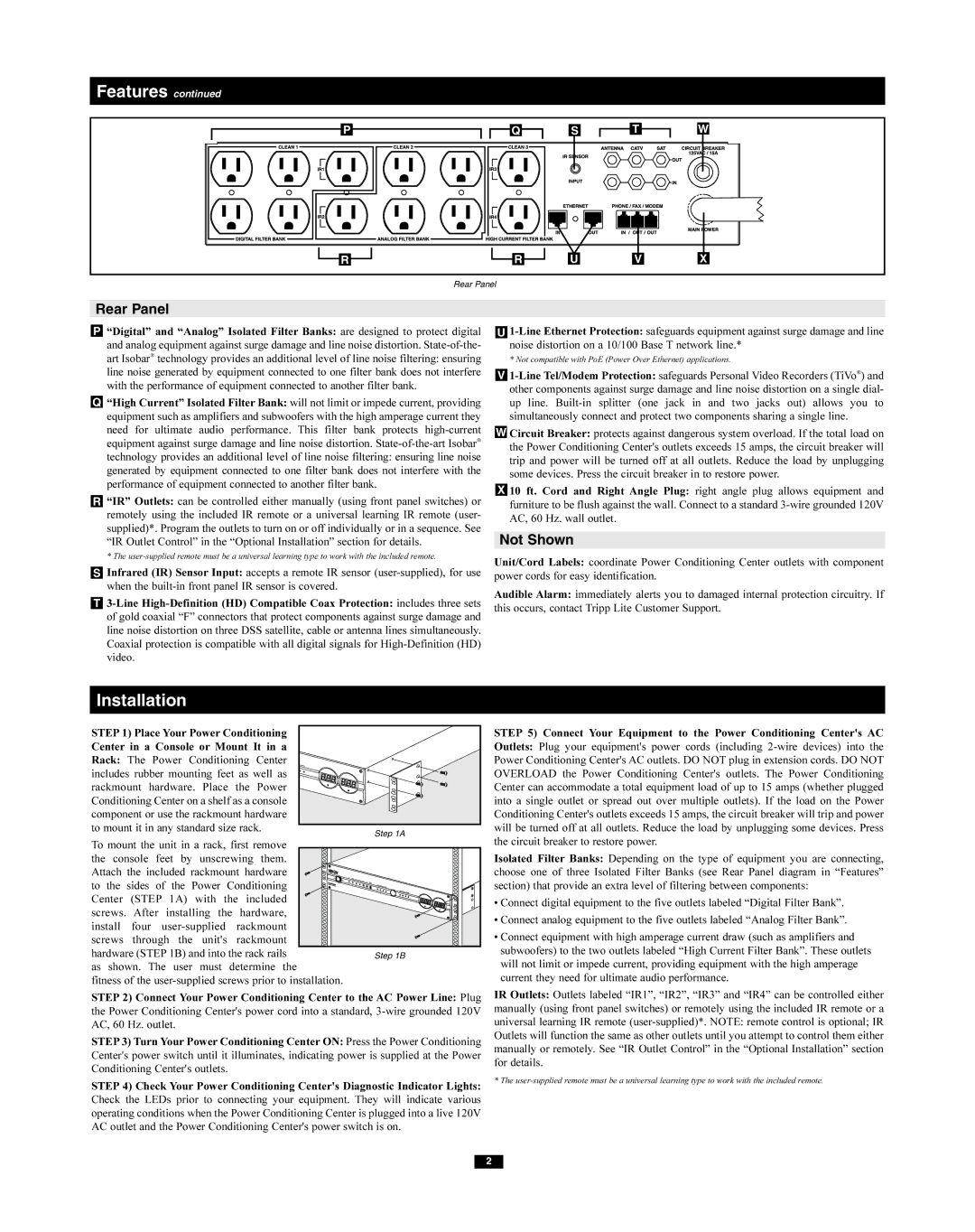
Rear Panel
Rear Panel
P“Digital” and “Analog” Isolated Filter Banks: are designed to protect digital and analog equipment against surge damage and line noise distortion.
Q“High Current” Isolated Filter Bank: will not limit or impede current, providing equipment such as amplifiers and subwoofers with the high amperage current they need for ultimate audio performance. This filter bank protects
R“IR” Outlets: can be controlled either manually (using front panel switches) or remotely using the included IR remote or a universal learning IR remote (user- supplied)*. Program the outlets to turn on or off individually or in a sequence. See “IR Outlet Control” in the “Optional Installation” section for details.
* The
SInfrared (IR) Sensor Input: accepts a remote IR sensor
T
U
* Not compatible with PoE (Power Over Ethernet) applications.
V
W Circuit Breaker: protects against dangerous system overload. If the total load on the Power Conditioning Center's outlets exceeds 15 amps, the circuit breaker will trip and power will be turned off at all outlets. Reduce the load by unplugging some devices. Press the circuit breaker in to restore power.
X 10 ft. Cord and Right Angle Plug: right angle plug allows equipment and furniture to be flush against the wall. Connect to a standard
Not Shown
Unit/Cord Labels: coordinate Power Conditioning Center outlets with component power cords for easy identification.
Audible Alarm: immediately alerts you to damaged internal protection circuitry. If this occurs, contact Tripp Lite Customer Support.
Installation
STEP 1) Place Your Power Conditioning |
|
Center in a Console or Mount It in a |
|
Rack: The Power Conditioning Center |
|
includes rubber mounting feet as well as |
|
rackmount hardware. Place the Power |
|
Conditioning Center on a shelf as a console |
|
component or use the rackmount hardware |
|
to mount it in any standard size rack. | Step 1A |
| |
To mount the unit in a rack, first remove |
|
the console feet by unscrewing them. |
|
Attach the included rackmount hardware |
|
to the sides of the Power Conditioning |
|
Center (STEP 1A) with the included |
|
screws. After installing the hardware, |
|
install four |
|
screws through the unit's rackmount |
|
hardware (STEP 1B) and into the rack rails | Step 1B |
as shown. The user must determine the |
|
fitness of the |
|
STEP 2) Connect Your Power Conditioning Center to the AC Power Line: Plug the Power Conditioning Center's power cord into a standard,
STEP3) Turn Your Power Conditioning Center ON: Press the Power Conditioning Center's power switch until it illuminates, indicating power is supplied at the Power Conditioning Center's outlets.
STEP 4) Check Your Power Conditioning Center's Diagnostic Indicator Lights: Check the LEDs prior to connecting your equipment. They will indicate various operating conditions when the Power Conditioning Center is plugged into a live 120V AC outlet and the Power Conditioning Center's power switch is on.
STEP 5) Connect Your Equipment to the Power Conditioning Center's AC Outlets: Plug your equipment's power cords (including
Isolated Filter Banks: Depending on the type of equipment you are connecting, choose one of three Isolated Filter Banks (see Rear Panel diagram in “Features” section) that provide an extra level of filtering between components:
•Connect digital equipment to the five outlets labeled “Digital Filter Bank”.
•Connect analog equipment to the five outlets labeled “Analog Filter Bank”.
•Connect equipment with high amperage current draw (such as amplifiers and subwoofers) to the two outlets labeled “High Current Filter Bank”. These outlets will not limit or impede current, providing equipment with the high amperage current they need for ultimate audio performance.
IR Outlets: Outlets labeled “IR1”, “IR2”, “IR3” and “IR4” can be controlled either manually (using front panel switches) or remotely using the included IR remote or a universal learning IR remote
* The
2