WARRANTY Lite product | ||||
REGISTRATION: | chance | |||
|
|
|
| — |
|
|
| a | |
online |
|
| for |
|
| .com/warranty | |||
| today |
|
| |
FREE | Tripp |
|
| |
|
|
| ||
register .tripplite |
|
| ||
a |
|
|
|
|
win |
|
|
|
|
to www |
|
|
|
|
Owner’s Manual
OMNI1300LCD
Digital UPS System
Not suitable for mobile applications
Important Safety Instructions
SAVE THESE INSTRUCTIONS
This manual contains instructions and warnings that should be followed during the installation, operation and storage of this product. Failure to heed these warnings will void the warranty.
UPS Location Warnings
•The UPS is designed for indoor use only in a controlled environment, away from excess moisture, extreme temperatures, conductive contaminants, dust or direct sunlight.
•Leave adequate space around all sides of the UPS for proper ventilation.
UPS Connection Warnings
•Connect the UPS directly to a properly grounded AC power outlet. Do not plug the UPS into itself; this will damage the UPS.
•Do not modify the UPS plug, and do not use an adapter that would eliminate the UPS ground connection.
•Do not use extension cords to connect the UPS to an AC outlet. The warranty will be void if anything other than Tripp Lite surge suppressors are used to connect the UPS to an outlet.
•If the UPS receives power from a
•The UPS contains its own energy source (battery). The output terminals may be live even when the UPS is not connected to an AC outlet.
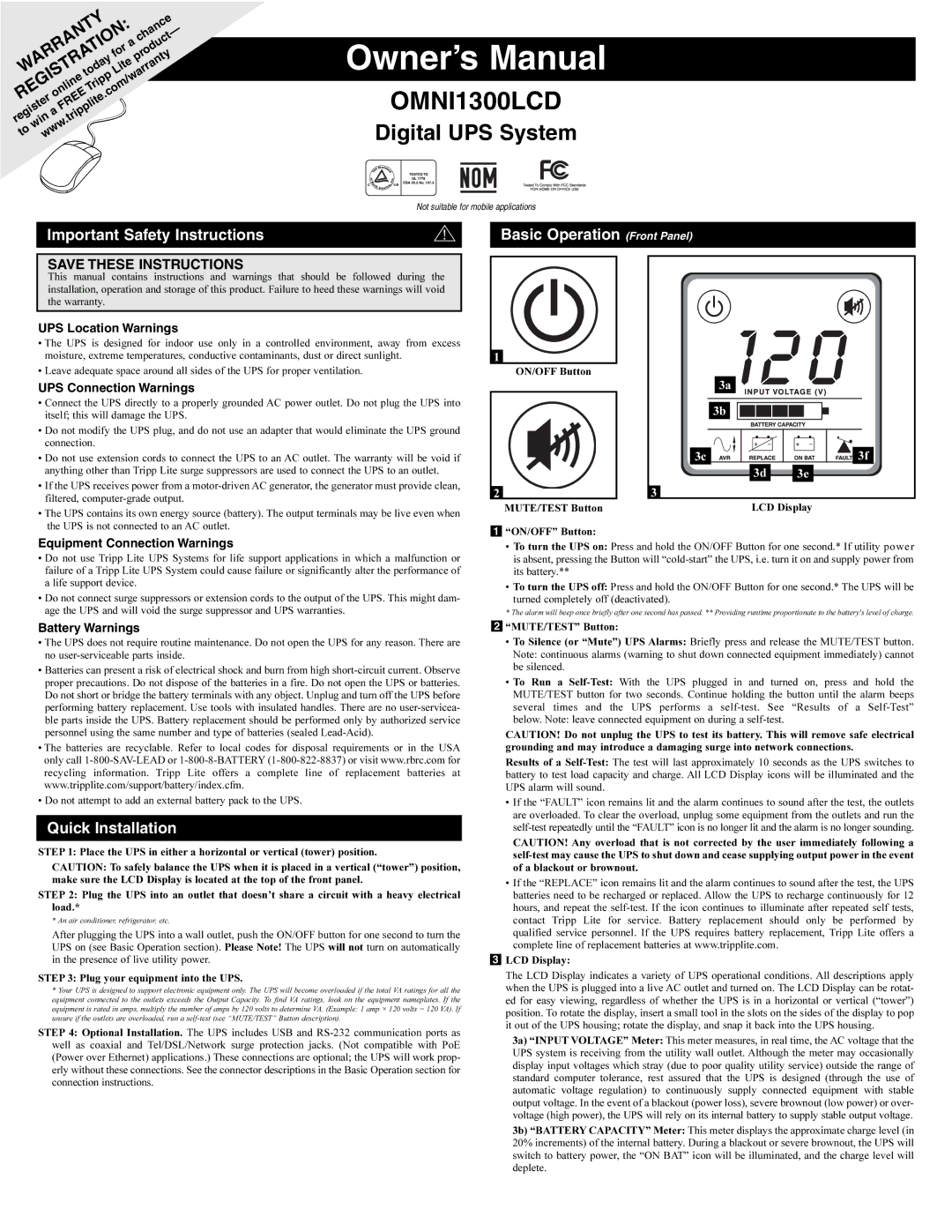
Basic Operation (Front Panel)
1 |
|
|
|
| ON/OFF Button |
|
|
|
| 3a |
|
|
| 3b |
|
| 3c |
| 3f |
|
| 3d | 3e |
2 | 3 |
|
|
| MUTE/TEST Button | LCD Display | |
1“ON/OFF” Button:
Equipment Connection Warnings
•Do not use Tripp Lite UPS Systems for life support applications in which a malfunction or failure of a Tripp Lite UPS System could cause failure or significantly alter the performance of a life support device.
•Do not connect surge suppressors or extension cords to the output of the UPS. This might dam- age the UPS and will void the surge suppressor and UPS warranties.
Battery Warnings
•To turn the UPS on: Press and hold the ON/OFF Button for one second.* If utility power is absent, pressing the Button will
•To turn the UPS off: Press and hold the ON/OFF Button for one second.* The UPS will be
turned completely off (deactivated).
* The alarm will beep once briefly after one second has passed. ** Providing runtime proportionate to the battery's level of charge.
2“MUTE/TEST” Button:
•The UPS does not require routine maintenance. Do not open the UPS for any reason. There are no
•Batteries can present a risk of electrical shock and burn from high
•The batteries are recyclable. Refer to local codes for disposal requirements or in the USA only call
•Do not attempt to add an external battery pack to the UPS.
Quick Installation
STEP 1: Place the UPS in either a horizontal or vertical (tower) position.
CAUTION: To safely balance the UPS when it is placed in a vertical (“tower”) position, make sure the LCD Display is located at the top of the front panel.
STEP 2: Plug the UPS into an outlet that doesn’t share a circuit with a heavy electrical load.*
* An air conditioner, refrigerator, etc.
After plugging the UPS into a wall outlet, push the ON/OFF button for one second to turn the UPS on (see Basic Operation section). Please Note! The UPS will not turn on automatically in the presence of live utility power.
STEP 3: Plug your equipment into the UPS.
*Your UPS is designed to support electronic equipment only. The UPS will become overloaded if the total VA ratings for all the equipment connected to the outlets exceeds the Output Capacity. To find VA ratings, look on the equipment nameplates. If the equipment is rated in amps, multiply the number of amps by 120 volts to determine VA. (Example: 1 amp × 120 volts = 120 VA). If unsure if the outlets are overloaded, run a
STEP 4: Optional Installation. The UPS includes USB and
•To Silence (or “Mute”) UPS Alarms: Briefly press and release the MUTE/TEST button.
Note: continuous alarms (warning to shut down connected equipment immediately) cannot be silenced.
•To Run a
CAUTION! Do not unplug the UPS to test its battery. This will remove safe electrical grounding and may introduce a damaging surge into network connections.
Results of a
•If the “FAULT” icon remains lit and the alarm continues to sound after the test, the outlets are overloaded. To clear the overload, unplug some equipment from the outlets and run the
CAUTION! Any overload that is not corrected by the user immediately following a
•If the “REPLACE” icon remains lit and the alarm continues to sound after the test, the UPS batteries need to be recharged or replaced. Allow the UPS to recharge continuously for 12 hours, and repeat the
3LCD Display:
The LCD Display indicates a variety of UPS operational conditions. All descriptions apply when the UPS is plugged into a live AC outlet and turned on. The LCD Display can be rotat- ed for easy viewing, regardless of whether the UPS is in a horizontal or vertical (“tower”) position. To rotate the display, insert a small tool in the slots on the sides of the display to pop it out of the UPS housing; rotate the display, and snap it back into the UPS housing.
3a) “INPUT VOLTAGE” Meter: This meter measures, in real time, the AC voltage that the UPS system is receiving from the utility wall outlet. Although the meter may occasionally display input voltages which stray (due to poor quality utility service) outside the range of standard computer tolerance, rest assured that the UPS is designed (through the use of automatic voltage regulation) to continuously supply connected equipment with stable output voltage. In the event of a blackout (power loss), severe brownout (low power) or over- voltage (high power), the UPS will rely on its internal battery to supply stable output voltage.
3b) “BATTERY CAPACITY” Meter: This meter displays the approximate charge level (in 20% increments) of the internal battery. During a blackout or severe brownout, the UPS will switch to battery power, the “ON BAT” icon will be illuminated, and the charge level will deplete.