Warranty | .com/warranty |
| |||||
Registration |
| a | Lite |
| |||
|
|
| today | for |
| ||
|
|
|
| Tripp |
| Owner’s Manual | |
|
| online FREE |
|
| |||
Register | .tripplite |
|
|
|
| ||
win |
|
|
|
|
| ||
| to |
|
|
|
|
| |
chance |
| www |
|
|
| Metered Rack PDU | |
|
|
|
|
| |||
product! |
|
|
|
| |||
|
|
|
|
|
| ||
Models:
PDUMV30 • PDUMV30HV • PDUV30HV • PDUMV20HV
1111 W. 35th Street Chicago, IL 60609 USA
(773)
Important Safety Instructions
SAVE THESE INSTRUCTIONS
This manual contains instructions and warnings that should be followed during the installation, operation and storage of this product. Failure to heed these instructions and warnings will void the product warranty.
Important Warnings
•The PDU provides convenient multiple outlets but it DOES NOT provide surge or line noise protection for connected equipment.
•The PDU is designed for indoor use only in a controlled environment away from excess moisture, temperature extremes, conductive contaminants, dust or direct sunlight.
•Use of this equipment in life support applications where failure of this equipment can reasonably be expected to cause the failure of the life support equipment or to significantly affect its safety or effectiveness is not recommended. Do not use this equipment in the presence of a flammable anesthetic mixture with air, oxygen or nitrous oxide.
•Do not connect the PDU to an ungrounded outlet or extension cords or adapters that eliminate the connection to ground.
•The power requirement for each piece of equipment connected to the PDU must not exceed the individual outlet's load rating.
•The total power requirement for equipment connected to the PDU must not exceed the maximum load rating for the PDU.
•Do not drill into or attempt to open any part of the PDU housing. There are no
•Do not attempt to modify the PDU, including the input plugs and power cables.
•Do not attempt to use the PDU if any part of it becomes damaged.
•Do not attempt to mount the PDU to an insecure or unstable surface.
•Never attempt to install electrical equipment during a thunderstorm.
Installation
Note: Regardless of configuration, the user must determine the fitness of hardware and procedures before mounting. The PDU and included hardware are designed for common rack and rack enclosure types and may not be appropriate for all applications.
1A Zero U Rack Configuration (Mounting Brackets). Prior to installation, |
determine the rack location in which the PDU is to be installed. Attach the |
mounting brackets to the back of the PDU as shown, using the included screws. |
To assist with proper positioning, the brackets have four screw holes each; |
make sure that the same two holes are used to attach each bracket to the PDU. |
After attaching the brackets, position the PDU in the rack and mount it by |
installing four |
1A |
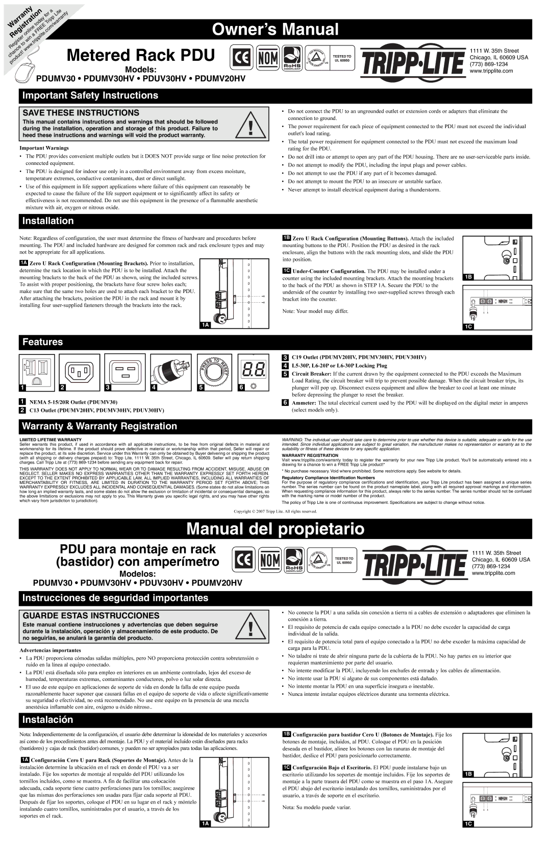
Features |
1B Zero U Rack Configuration (Mounting Buttons). Attach the included mounting buttons to the PDU. Position the PDU as desired in the rack enclosure, align the buttons with the rack mounting slots, and slide the PDU into position.
1C
Note: Your model may differ.
1B |
1C |
1 | 2 | 3 | 4 | 5 | 6 |
1NEMA
2C13 Outlet (PDUMV20HV, PDUMV30HV, PDUV30HV)
3C19 Outlet (PDUMV20HV, PDUMV30HV, PDUV30HV)
4
5Circuit Breaker: If the current drawn by the equipment connected to the PDU exceeds the Maximum Load Rating, the circuit breaker will trip to prevent possible damage. When the circuit breaker trips, its plunger will pop up. Disconnect excess equipment and allow the breaker to cool at least one minute before depressing the plunger to reset the breaker.
6Ammeter: The total electrical current used by the PDU will be displayed on the digital meter in amperes (select models only).
Warranty & Warranty Registration
LIMITED LIFETIME WARRANTY
Seller warrants this product, if used in accordance with all applicable instructions, to be free from original defects in material and workmanship for its lifetime. If the product should prove defective in material or workmanship within that period, Seller will repair or replace the product, at its sole discretion. Service under this Warranty can only be obtained by Buyer delivering or shipping the product (with all shipping or delivery charges prepaid) to: Tripp Lite, 1111 W. 35th Street, Chicago, IL 60609. Seller will pay return shipping charges. Call Tripp Lite at (773)
THIS WARRANTY DOES NOT APPLY TO NORMAL WEAR OR TO DAMAGE RESULTING FROM ACCIDENT, MISUSE, ABUSE OR NEGLECT. SELLER MAKES NO EXPRESS WARRANTIES OTHER THAN THE WARRANTY EXPRESSLY SET FORTH HEREIN. EXCEPT TO THE EXTENT PROHIBITED BY APPLICABLE LAW, ALL IMPLIED WARRANTIES, INCLUDING ALL WARRANTIES OF MERCHANTABILITY OR FITNESS, ARE LIMITED IN DURATION TO THE WARRANTY PERIOD SET FORTH ABOVE; THIS WARRANTY EXPRESSLY EXCLUDES ALL INCIDENTAL AND CONSEQUENTIAL DAMAGES. (Some states do not allow limitations on how long an implied warranty lasts, and some states do not allow the exclusion or limitation of incidental or consequential damages, so the above limitations or exclusions may not apply to you. This Warranty gives you specific legal rights, and you may have other rights which vary from jurisdiction to jurisdiction).
WARNING: The individual user should take care to determine prior to use whether this device is suitable, adequate or safe for the use intended. Since individual applications are subject to great variation, the manufacturer makes no representation or warranty as to the suitability or fitness of these devices for any specific application.
WARRANTY REGISTRATION
Visit www.tripplite.com/warranty today to register the warranty for your new Tripp Lite product. You'll be automatically entered into a drawing for a chance to win a FREE Tripp Lite product!*
* No purchase necessary. Void where prohibited. Some restrictions apply. See website for details.
Regulatory Compliance Identification Numbers
For the purpose of regulatory compliance certifications and identification, your Tripp Lite product has been assigned a unique series number. The series number can be found on the product nameplate label, along with all required approval markings and information. When requesting compliance information for this product, always refer to the series number. The series number should not be confused with the marking name or model number of the product.
The policy of Tripp Lite is one of continuous improvement. Specifications are subject to change without notice.
Copyright © 2007 Tripp Lite. All rights reserved.
Manual del propietario
PDU para montaje en rack (bastidor) con amperímetro
Modelos:
PDUMV30 • PDUMV30HV • PDUV30HV • PDUMV20HV
1111 W. 35th Street Chicago, IL 60609 USA
(773)
Instrucciones de seguridad importantes
GUARDE ESTAS INSTRUCCIONES
Este manual contiene instrucciones y advertencias que deben seguirse durante la instalación, operación y almacenamiento de este producto. De no seguirlas, se anulará la garantía del producto.
Advertencias importantes
•La PDU proporciona cómodas salidas múltiples, pero NO proporciona protección contra sobretensión o ruido en la línea al equipo conectado.
•La PDU está diseñada sólo para empleo en interiores en un ambiente controlado, lejos del exceso de humedad, temperaturas extremas, contaminantes conductores, polvo o luz solar directa.
•El uso de este equipo en aplicaciones de soporte de vida en donde la falla de este equipo pueda razonablemente hacer suponer que causará fallas en el equipo de soporte de vida o afecte significativamente su seguridad o efectividad, no está recomendado. No use este equipo en la presencia de una mezcla anestésica inflamable con aire, oxigeno u óxido nitroso..
Instalación
•No conecte la PDU a una salida sin conexión a tierra ni a cables de extensión o adaptadores que eliminen la conexión a tierra.
•El requisito de potencia de cada equipo conectado a la PDU no debe exceder la capacidad de carga individual de la salida.
•El requisito de potencia total para el equipo conectado a la PDU no debe exceder la máxima capacidad de carga para la PDU.
•No taladre ni trate de abrir ninguna parte de la cubierta de la PDU. No hay partes en su interior que requieran mantenimiento por parte del usuario.
•No intente modificar la PDU, incluyendo los enchufes de entrada y los cables de alimentación.
•No intente usar la PDU si alguno de sus componentes está dañado.
•No intente montar la PDU en una superficie insegura o inestable.
•Nunca intente instalar equipos eléctricos durante una tormenta eléctrica.
Nota: Independientemente de la configuración, el usuario debe determinar la idoneidad de los materiales y accesorios así como de los procedimientos antes del montaje. La PDU y el material incluido están diseñados para racks (bastidores) y cajas de rack (bastidor) comunes, y pueden no ser apropiados para todas las aplicaciones.
1A Configuración Cero U para Rack (Soportes de Montaje). Antes de la instalación determine la ubicación en el rack en donde el PDU va a ser instalado. Fije los soportes de montaje al respaldo del PDU utilizando los tornillos incluidos, como se muestra. A fin de facilitar una colocación adecuada, cada soporte tiene cuatro perforaciones para los tornillos; asegúrese que las mismas dos perforaciones son usadas para fijar cada soporte al PDU. Después de fijar los soportes, coloque el PDU en su lugar en el rack y móntelo instalando cuatro tornillos, suministrados por el usuario, a través de los soportes en el rack.
1A
1B Configuración para bastidor Cero U (Botones de Montaje). Fije los botones de montaje, incluidos, al PDU. Coloque el PDU en la posición deseada en el bastidor, alinee los botones con las ranuras de montaje del bastidor, deslice el PDU para posicionarlo correctamente.
1C Configuración Bajo el Escritorio. El PDU puede instalarse bajo un escritorio utilizando los soportes de montaje incluidos. Fije los soportes de montaje a la parte trasera del PDU como se muestra en el paso 1A. Asegure el PDU abajo del escritorio instalando dos tornillos, suministrados por el usuario, a través de soporte en el escritorio.
Nota: Su modelo puede variar.
1B |
1C |