Installation
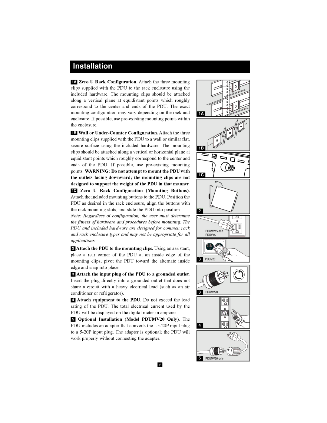
1A Zero U Rack Configuration. Attach the three mounting clips supplied with the PDU to the rack enclosure using the included hardware. The mounting clips should be attached along a vertical plane at equidistant points which roughly correspond to the center and ends of the PDU. The exact mounting configuration may vary depending on the rack and enclosure. If possible, use
1B Wall or
Note: Regardless of configuration, the user must determine the fitness of hardware and procedures before mounting. The PDU and included hardware are designed for common rack and rack enclosure types and may not be appropriate for all applications.
2Attach the PDU to the mounting clips. Using an assistant, place a rear corner of the PDU at an inside edge of the mounting clips, pivot the PDU toward the alternate inside edge and snap into place.
3Attach the input plug of the PDU to a grounded outlet. Insert the plug directly into a grounded outlet that does not share a circuit with a heavy electrical load (such as an air conditioner or refrigerator).
4Attach equipment to the PDU. Do not exceed the load rating of the PDU. The total electrical current used by the PDU will be displayed on the digital meter in amperes.
5Optional Installation (Model PDUMV20 Only). The PDU includes an adapter that converts the
1A |
1B |
1C |
2 |
PDUMV15 and |
PDUV15 |
3 | PDUV20 |
3 | PDUMV20 |
4 |
|
5PDUMV20 only
2