Tripp Lite Power Strips
Standard Models
1111 W. 35th Street Chicago, IL 60609 USA Customer Support: (773)
Français : p. 2; Español: p. 3
Your Power Strip is designed to provide convenient multiple AC outlets.
SSPower Strips models (e.g. the
ELECTRICAL CONNECTION
Plug your Power Strip into a standard, grounded electrical outlet. DO NOT plug your Power Strip into
EQUIPMENT CONNECTION
Plug your equipment into the Power Strip’s AC receptacles. DO NOT plug in equipment that draws more total amps than your Power Strip's amperage rating (see label on Power Strip for amperage rating), or you will trip the circuit breaker. If the circuit breaker trips, remove overload and depress breaker to reset. Leave enough clearance at the end of the Power Strip to allow the circuit breaker to operate normally.
Note: Select models with a power switch feature a protective switch cover. To access the switch, simply flip open the attached cover.
WALL MOUNTING
All standard Power Strip models feature clips for horizontal or vertical mounting on a variety of surfaces. The user must supply other mounting hardware (screws, etc.) and determine their suitability for use with the chosen mounting surface.
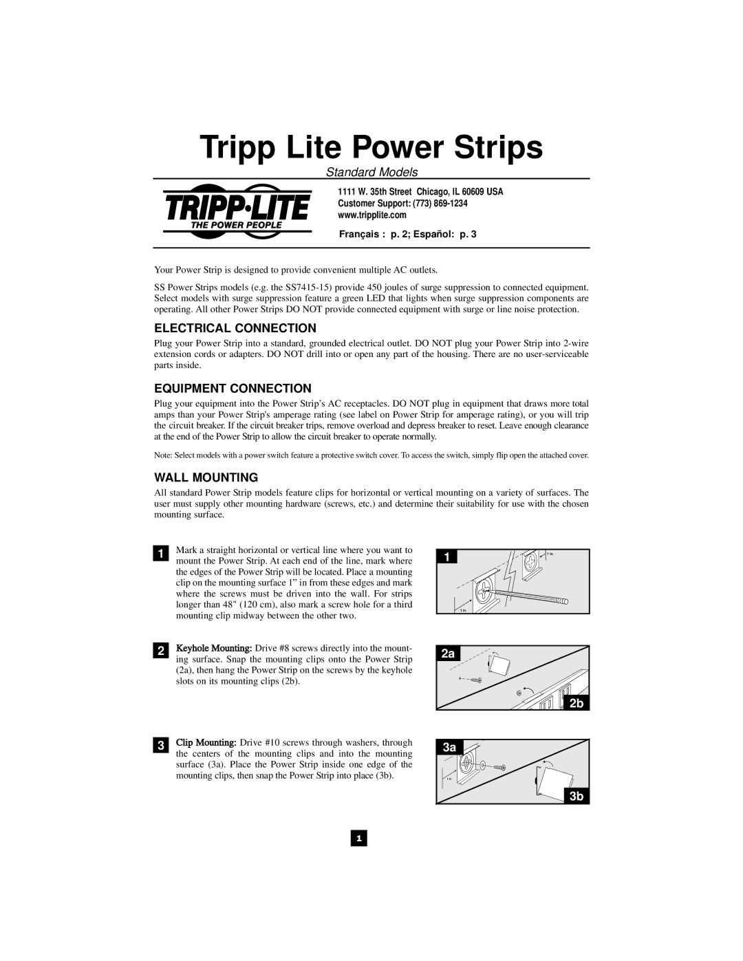
1Mark a straight horizontal or vertical line where you want to mount the Power Strip. At each end of the line, mark where the edges of the Power Strip will be located. Place a mounting clip on the mounting surface 1” in from these edges and mark where the screws must be driven into the wall. For strips longer than 48" (120 cm), also mark a screw hole for a third mounting clip midway between the other two.
1 |
2Keyhole Mounting: Drive #8 screws directly into the mount- ing surface. Snap the mounting clips onto the Power Strip (2a), then hang the Power Strip on the screws by the keyhole slots on its mounting clips (2b).
3Clip Mounting: Drive #10 screws through washers, through the centers of the mounting clips and into the mounting surface (3a). Place the Power Strip inside one edge of the mounting clips, then snap the Power Strip into place (3b).
2a
![]()
![]() 2b
2b
3a![]()
3b
1