Manuals
/
Tripp Lite
/
Computer Equipment
/
Power Supply
Tripp Lite
SUPDMB12KHW
owner manual
Primary Parallel PDU Module, Secondary Parallel PDU Module
Models:
SUPDMB12KHW
1
3
24
24
Download
24 pages
30.74 Kb
1
2
3
4
5
6
7
8
Warranty
Maintenance
Page 3
Image 3
Page 2
Page 4
Page 3
Image 3
Page 2
Page 4
Contents
Owner’s Manual
Parallel PDU Kit SmartOnline UPS Systems 6kVA
Primary & Secondary Parallel PDU Units
Location Warnings
Maintenance Warning
6kVA Redundant Configuration 6kVA max load
12kVA Non-Redundant Configuration 12kVA max load
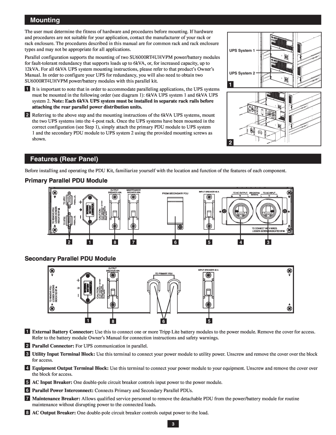
2 Parallel Connector For UPS communication in parallel
Primary Parallel PDU Module
Secondary Parallel PDU Module
PARALLEL SLAVE
6 Power ON UPS system 1, being sure that the output breakers are OFF
UPS systems
PARALLEL MASTER
UPS Removal
Manual Bypass Operation for UPS maintenance or replacement
2-Year Limited
Service
WARRANTY REGISTRATION
Storage
Manual del propietario
Kit de PDU paralelo para Sistemas UPS SmartOnline 6kVA
Unidades de PDU paralelos principales y secundarios
Advertencias de mantenimiento
Configuración redundante para 6kVA 6kVA de carga máx
Advertencias de ubicación
Advertencias sobre la conexión de equipos
Módulo de PDU paralelo secundario
Módulo de PDU paralelo principal
sistema UPS 2 mostrará “Paralelo Esclavo”
Únicamente la PDU principal
Extracción del UPS
Conformidad con las regulaciones sobre números de identificación
Almacenamiento
Servicio
Garantía limitada por 2 años
Manuel de l’utilisateur
Ensemble de PDU parallèle pour systèmes d’ASI SmartOnline 6kVA
Unités PDU parallèles principales et secondaires
Avertissements concernant l’entretien
Avertissements concernant l’emplacement de la PDU
Configuration redondante de 6kVA charge maximale de 6kVA
Avertissements concernant le branchement de l’équipement
Module de la PDU parallèle secondaire
Module de la PDU parallèle principal
1 En vous assurant que tous les interrupteurs sont éteints et que toutes les unités sont coupées, reportez-vous à la section « Montage » du manuel. Montez d’abord les systèmes d’ASI puis les PDU parallèles principale et secondaire
État de la seortie Mode puissance
Retrait de l’ASI
État de la de sortie
fonctionnement normal
Entreposage
Garantie limitée de 2 ans
Numéros d’identification de conformité réglementaire
Руководство по эксплуатации
Набор для параллельного включения ИБП SmartOnline 6 кВА
Первичные и вторичные блоки PDU при параллельном включении
Правила безопасности при выборе места для установки
Правила безопасности при подключении оборудования
Меры предосторожности при обслуживании
Первичный блок PDU параллельной конфигурации
Вторичный блок PDU параллельной конфигурации
2 Разъем для параллельного подключения Для связи с параллельным ИБП
Page
Снятие ИБП
Ручное переключение на работу в обход для обслуживания или замены ИБП
Сервисное обслуживание
Хранение
Top
Page
Image
Contents