Section 2: Assembly
Chart 1: FUEL MIXTURE
(Mixture Ratio is 24 parts gasoline to
1 part
U.S. Gas | U.S. Oil |
|
|
1 Gal. | 5 oz. |
2 Gal. | 11 oz. |
Metric Petrol | Metric Oil |
|
|
4 liters | 167 ml |
8 liters | 333 ml |
4.Do not mix fuel directly in engine fuel tank. Always use a clean,
•To Mix:
A.Fill a clean, approved container one quarter full with recommended gasoline.
B.Add recommended amount of oil per Chart 1: FUEL MIXTURE.
C.Screw cap on container and shake vigorously. Then unscrew cap and fill container with gasoline per Chart 1: FUEL MIXTURE. Screw on cap and shake again. Once mixed, oil and gasoline will not separate.
Fill Fuel Tank:
1. Engine must be cool. Clean area |
around fuel tank cap and remove cap. |
Insert a clean funnel into the fuel tank. |
2. Slowly pour gasoline/oil mixture into |
fuel tank. Fill tank no higher than 1/2" |
from top of tank to allow for gasoline ex- |
STEP 4: To Make Borders and Edges, Install the Edger Attachment
To create borders or edges near walks, driveways, flower beds, etc., you must remove the four tine sections and install the Edger Attachment (this attachment was supplied with the unit – see Page 5).
To Install the Edger Attachment:
1.Gather together the following parts (see Figure 4): (A) Border/Edger Tine; (B) Long Bushing; (C) Border/Edger Wheel and (D) Short Bushing.
2.Prop the machine carefully on the front of the tubular carrying handle. The work surface should be firm and flat. NOTE: Usually the Border/Edger Tine is mounted on the
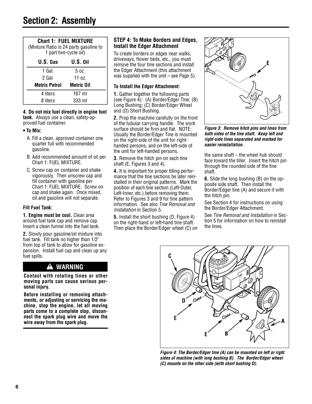
3.Remove the hitch pin on each tine shaft (E, Figures 3 and 4).
4.It is important for proper tilling perfor- mance that the tine sections be later rein- stalled in their original patterns. Mark the position of each tine section
5.Install the short bushing (D, Figure 4) on the
E |
Figure 3: Remove hitch pins and tines from both sides of the tine shaft. Keep left and right-side tines separated and marked for easier reinstallation.
the same shaft – the wheel hub should face toward the tiller. Insert the hitch pin through the rounded side of the tine shaft.
6.Slide the long bushing (B) on the op- posite side shaft. Then install the Border/Edger tine (A) and secure it with the hitch pin.
See Section 4 for instructions on using the Border/Edger Attachment.
See Tine Removal and Installation in Sec- tion 5 for information on how to reinstall the tines.
pansion. Install fuel cap and clean up any |
fuel spills. |
WARNING
Contact with rotating tines or other moving parts can cause serious per- sonal injury.
Before installing or removing attach- ments, or adjusting or servicing the ma- chine, stop the engine, let all moving parts come to a complete stop, discon- nect the spark plug wire and move the wire away from the spark plug.
C |
|
D |
|
E | A |
| |
E | B |
Figure 4: The Border/Edger tine (A) can be mounted on left or right sides of machine (with long bushing B). The Border/Edger wheel
(C) mounts on the other side (with short bushing D).
6