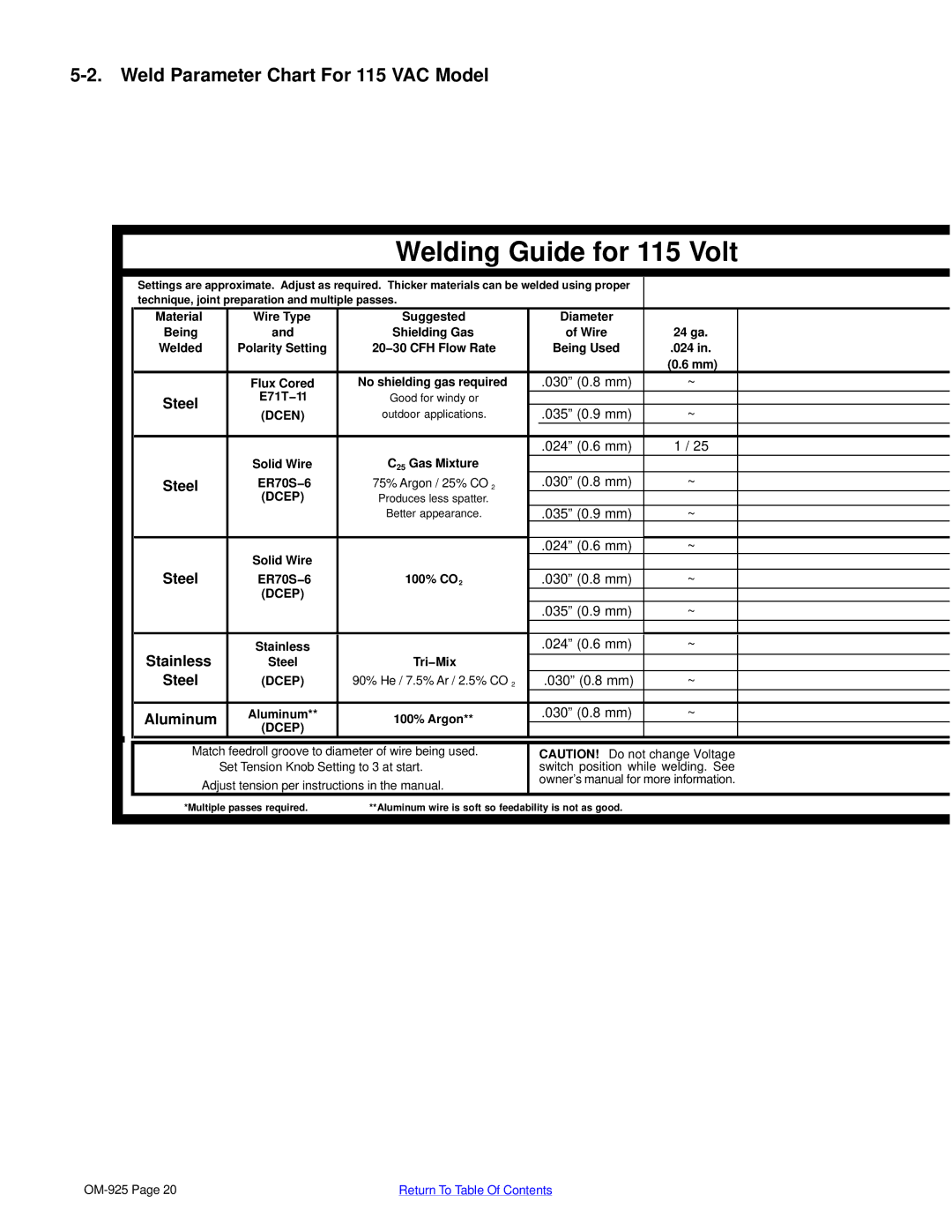
5-2. Weld Parameter Chart For 115 VAC Model
Welding Guide for 115 Volt
|
|
|
|
|
|
|
|
|
|
|
|
|
|
|
| Settings are approximate. Adjust as required. Thicker materials can be welded using proper |
|
| |||||
|
|
|
| technique, joint preparation and multiple passes. |
|
|
|
| |||
|
|
|
| Material | Wire Type |
| Suggested |
| Diameter |
|
|
|
|
|
| Being | and |
| Shielding Gas |
| of Wire | 24 ga. |
|
|
|
|
| Welded | Polarity Setting | 20−30 CFH Flow Rate |
| Being Used | .024 in. |
| |
|
|
|
|
|
|
|
|
|
| (0.6 mm) |
|
|
|
|
|
| Flux Cored | No shielding gas required |
| .030” (0.8 mm) | ~ |
| |
|
|
|
| Steel | E71T−11 |
| Good for windy or |
|
|
|
|
|
|
|
| (DCEN) |
| outdoor applications. |
| .035” (0.9 mm) | ~ |
| |
|
|
|
|
|
|
|
| ||||
|
|
|
|
|
|
|
|
|
|
|
|
|
|
|
|
|
|
|
|
| .024” (0.6 mm) | 1 / 25 |
|
|
|
|
|
| Solid Wire |
| C25 Gas Mixture |
|
|
|
|
|
|
|
| Steel | ER70S−6 | 75% Argon / 25% CO 2 |
| .030” (0.8 mm) | ~ |
| |
|
|
|
|
| (DCEP) |
| Produces less spatter. |
|
|
|
|
|
|
|
|
|
|
| Better appearance. |
| .035” (0.9 mm) | ~ |
|
|
|
|
|
|
|
|
|
|
|
|
|
|
|
|
|
| Solid Wire |
|
|
| .024” (0.6 mm) | ~ |
|
|
|
|
| Steel |
|
|
|
|
|
| |
|
|
|
| ER70S−6 |
| 100% CO2 |
| .030” (0.8 mm) | ~ |
| |
|
|
|
|
| (DCEP) |
|
|
|
|
|
|
|
|
|
|
|
|
|
|
| .035” (0.9 mm) | ~ |
|
|
|
|
|
|
|
|
|
|
|
|
|
|
|
|
| Stainless | Stainless |
|
|
| .024” (0.6 mm) | ~ |
|
|
|
|
| Steel |
| Tri−Mix |
|
|
|
| |
|
|
|
| Steel | (DCEP) | 90% He / 7.5% Ar / 2.5% CO 2 |
| .030” (0.8 mm) | ~ |
| |
|
|
|
|
|
|
|
|
|
|
|
|
|
|
|
| Aluminum | Aluminum** |
| 100% Argon** |
| .030” (0.8 mm) | ~ |
|
|
|
|
| (DCEP) |
|
|
|
|
| ||
|
|
|
|
|
|
|
|
|
|
| |
Match feedroll groove to diameter of wire being used. Set Tension Knob Setting to 3 at start.
Adjust tension per instructions in the manual.
CAUTION! Do not change Voltage switch position while welding. See owner’s manual for more information.
*Multiple passes required. | **Aluminum wire is soft so feedability is not as good. |
|
|
Return To Table Of Contents |