Manuals
/
Hobart Welding Products
/
Power Tools
/
Welder
Hobart Welding Products
OM-925 217 694A
manual
Circuit Diagram For 230 VAC Model
Models:
OM-925 217 694A
1
34
52
52
Download
52 pages
30.74 Kb
31
32
33
34
35
36
37
38
Troubleshooting
Specs
Poor Weld Bead Characteristics
Install
Parts list
Electrical Diagram
Symbol Usage
Threading Welding Wire
Safety
Service
Page 34
Image 34
217
755-A
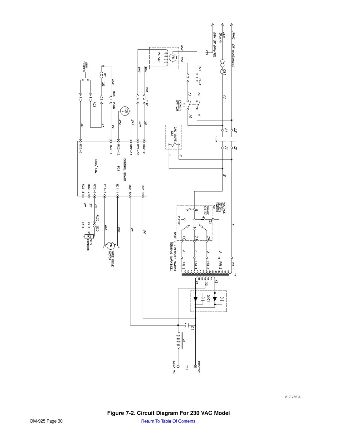
Figure
7-2.
Circuit Diagram For 230 VAC Model
OM-925
Page 30
Return To Table Of Contents
Page 33
Page 35
Page 34
Image 34
Page 33
Page 35
Contents
Processes
OM-925
Description
From Hobart to You
Table of Contents
Options and Accessories Warranty
Arc Welding Hazards
Symbol Usage
Marks a special safety message
Electric Shock can kill
Flying Metal can injure eyes
ARC Rays can burn eyes and skin
Welding can cause fire or explosion
Buildup of GAS can injure or kill
California Proposition 65 Warnings
EMF Information
Principal Safety Standards
About Pacemakers
Identifie un message de sécurité particulier
− Consignes DE Sécurité − À Lire Avant Utilisation
LES Pièces Chaudes peuvent cau- ser des brûlures graves
LE Soudage peut causer un incen- die ou une explosion
LES Particules Projetées peu- vent blesser les yeux
LE Bruit peut affecter l’ouïe
’EMPLOI Excessif peut Faire
Risque D’INCENDIE OU D’EXPLO
LA Chute DE L’APPAREIL peut blesser
LES Pièces Mobiles peuvent cau- ser des blessures
Information sur les champs électromagnétiques
Principales normes de sécurité
Consignes relatives aux stimulateurs cardiaques
Specifications
− Specifications
VAC Model
Output Duty Cycle %
Duty Cycle And Overheating
Amperes
VAC Model Output Amperes
Volt-Ampere Curves
Voltage
− Installation
Installing Welding Gun Installing Work Clamp
Process/Polarity Table
Changing Polarity
Installing Gas Supply
Is required
Do not move or operate unit where it could tip
= GND/PE
Electrical Service Guide For 230 VAC Model
Installing Wire Spool And Adjusting Hub Tension
Threading Welding Wire
Hold wire tightly to keep it From unraveling
− Operation
Controls
Weld Parameter Chart For 115 VAC Model
Steel
20 ga 18 ga 16 ga 11 ga
Inch
Weld Parameter Chart For 230 VAC Model
Wire Welding Package
18 ga 16 ga 11 ga 048 060 Inch
Disconnect power before maintaining
− Maintenance &TROUBLESHOOTING
Routine Maintenance
Overload Protection Drive Motor Protection
Turn Off power before replacing contact tip
Changing Drive Roll Or Wire Inlet Guide
Replacing Gun Contact Tip
Disconnect gun from unit
Cleaning Or Replacing Gun Liner
To Reassemble Gun
Replacing Switch And/Or Head Tube
Troubleshooting Table
Trouble Remedy
− Electrical Diagram
Circuit Diagram For 115 VAC Model
Circuit Diagram For 230 VAC Model
− MIG Welding Gmaw Guidelines
Typical MIG Process Connections
Thickness to Amperage a
Typical MIG Process Control Settings
Wire Size Amperage Range
Select Voltage
Holding And Positioning Welding Gun
Conditions That Affect Weld Bead Shape
Good Weld Bead Characteristics
Poor Weld Bead Characteristics
Gun Movement During Welding
Troubleshooting − Excessive Penetration
Troubleshooting − Excessive Spatter
Troubleshooting − Porosity
Possible Causes Corrective Actions
Troubleshooting − Incomplete Fusion
Troubleshooting − Lack Of Penetration
Troubleshooting − Burn-Through
Troubleshooting − Waviness Of Bead
Troubleshooting − Distortion
Common MIG Shielding Gases
Troubleshooting Guide For Semiautomatic Welding Equipment
Application
Welding arc not stable Wire slipping in drive rolls
Return To Table Of Contents
− Parts List
Main Assembly
Dia Part
H-10 Gun
Options
Optional Drive Rolls
195
Page
Service
Support
Contact your Distributor for
Hobart Welding Products
Top
Page
Image
Contents