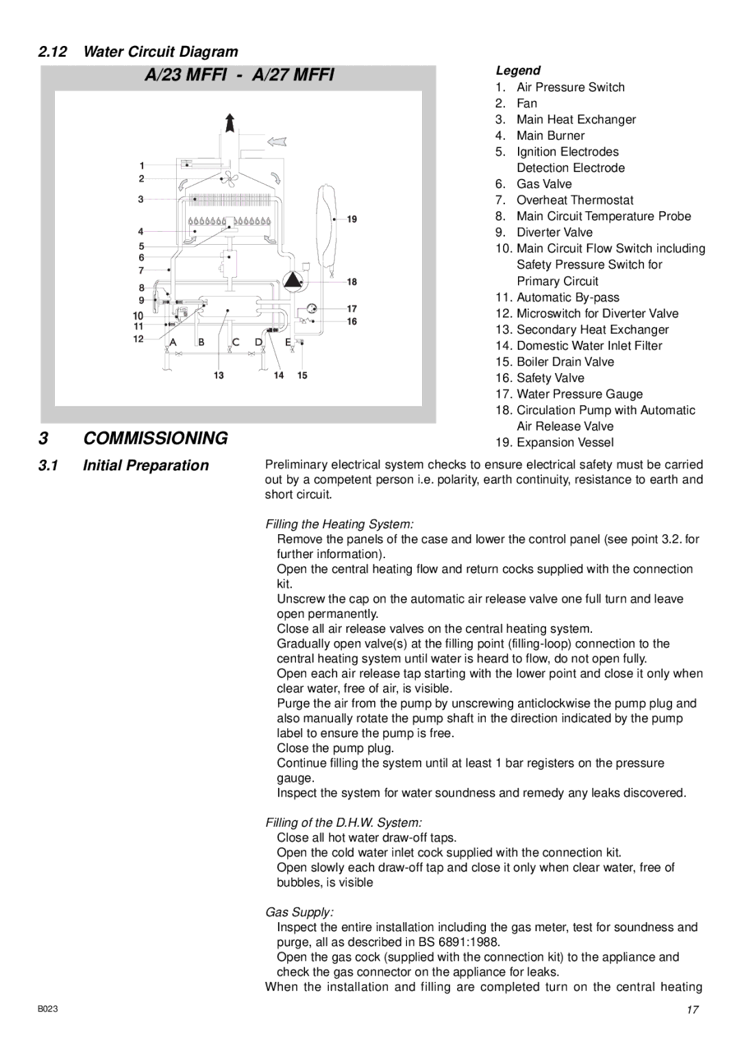
2.12Water Circuit Diagram
A/23 MFFI
3 COMMISSIONING
3.1Initial Preparation
- A/27 MFFI | Legend | |
| 1. | Air Pressure Switch |
| 2. | Fan |
| 3. | Main Heat Exchanger |
| 4. | Main Burner |
| 5. | Ignition Electrodes |
|
| Detection Electrode |
| 6. | Gas Valve |
| 7. | Overheat Thermostat |
| 8. | Main Circuit Temperature Probe |
| 9. | Diverter Valve |
| 10. | Main Circuit Flow Switch including |
|
| Safety Pressure Switch for |
|
| Primary Circuit |
| 11. | Automatic |
| 12. | Microswitch for Diverter Valve |
| 13. | Secondary Heat Exchanger |
| 14. | Domestic Water Inlet Filter |
| 15. | Boiler Drain Valve |
| 16. | Safety Valve |
| 17. | Water Pressure Gauge |
| 18. | Circulation Pump with Automatic |
|
| Air Release Valve |
| 19. | Expansion Vessel |
Preliminary electrical system checks to ensure electrical safety must be carried out by a competent person i.e. polarity, earth continuity, resistance to earth and short circuit.
Filling the Heating System:
Remove the panels of the case and lower the control panel (see point 3.2. for further information).
Open the central heating flow and return cocks supplied with the connection kit.
Unscrew the cap on the automatic air release valve one full turn and leave open permanently.
Close all air release valves on the central heating system.
Gradually open valve(s) at the filling point
Open each air release tap starting with the lower point and close it only when clear water, free of air, is visible.
Purge the air from the pump by unscrewing anticlockwise the pump plug and also manually rotate the pump shaft in the direction indicated by the pump label to ensure the pump is free.
Close the pump plug.
Continue filling the system until at least 1 bar registers on the pressure gauge.
Inspect the system for water soundness and remedy any leaks discovered.
Filling of the D.H.W. System: Close all hot water
Open the cold water inlet cock supplied with the connection kit.
Open slowly each
Gas Supply:
Inspect the entire installation including the gas meter, test for soundness and purge, all as described in BS 6891:1988.
Open the gas cock (supplied with the connection kit) to the appliance and check the gas connector on the appliance for leaks.
When the installation and filling are completed turn on the central heating
B023 | 17 |