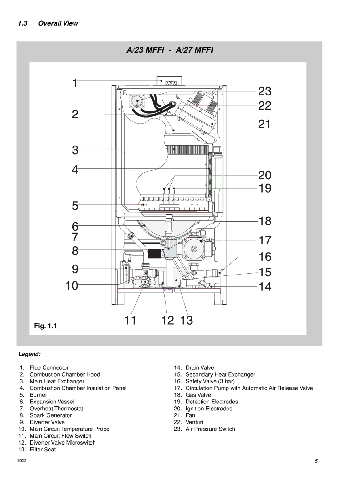
1.3Overall View
A/23 MFFI - A/27 MFFI
Fig. 1.1
Legend: |
|
| |
1. | Flue Connector | 14. | Drain Valve |
2. | Combustion Chamber Hood | 15. | Secondary Heat Exchanger |
3. | Main Heat Exchanger | 16. | Safety Valve (3 bar) |
4. | Combustion Chamber Insulation Panel | 17. | Circulation Pump with Automatic Air Release Valve |
5. | Burner | 18. | Gas Valve |
6. | Expansion Vessel | 19. | Detection Electrodes |
7. | Overheat Thermostat | 20. | Ignition Electrodes |
8. | Spark Generator | 21. | Fan |
9. | Diverter Valve | 22. | Venturi |
10. | Main Circuit Temperature Probe | 23. | Air Pressure Switch |
11.Main Circuit Flow Switch
12.Diverter Valve Microswitch
13.Filter Seat
B023 | 5 |
