chamber visually.
4- Visual check of the combustion: clean burners if necessary.
5- With reference to point 3, dismantle and clean the combustion chamber if necessary.
6- With reference to point 4, dismantle and clean the injectors if necessary.
7- Visual check of the primary heat exchanger:
-check for overheating of the exchangers fins;
-clean the exhaust side of the exchanger and fan if necessary.
8- Regulate the gas pressure, ignition pressure, partial flame, maximum flame.
9- Check proper operation of the heating safety system:
-maximum safety temperature;
-maximum safety pressure.
10- Check the proper operation of the gas safety system:
-gas or flame safety device;
-gas valve safety device.
11- Check that the electrical connections have been made in compliance with the instructions shown in the installation instructions.
12- Check the efficiency of the hot water supply (flow and temperature).
13- Check general operation of the appliance.
14- Check the exhaust system for the combustion products.
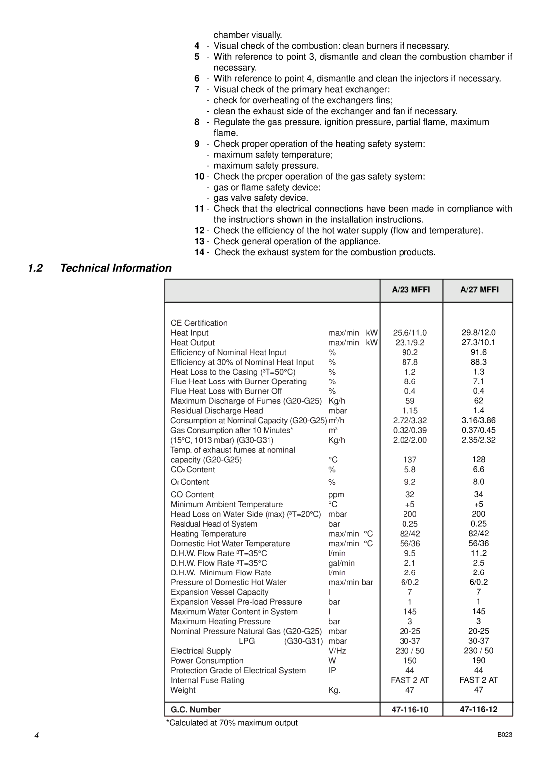
1.2Technical Information
|
|
|
|
| A/23 MFFI | A/27 MFFI |
|
|
|
|
|
|
|
|
|
| CE Certification |
|
|
|
|
|
|
| Heat Input |
| max/min | kW | 25.6/11.0 | 29.8/12.0 |
|
| Heat Output |
| max/min | kW | 23.1/9.2 | 27.3/10.1 |
|
| Efficiency of Nominal Heat Input | % |
| 90.2 | 91.6 |
| |
| Efficiency at 30% of Nominal Heat Input | % |
| 87.8 | 88.3 |
| |
| Heat Loss to the Casing (³T=50°C) | % |
| 1.2 | 1.3 |
| |
| Flue Heat Loss with Burner Operating | % |
| 8.6 | 7.1 |
| |
| Flue Heat Loss with Burner Off |
| % |
| 0.4 | 0.4 |
|
| Maximum Discharge of Fumes | Kg/h |
| 59 | 62 |
| |
| Residual Discharge Head |
| mbar |
| 1.15 | 1.4 |
|
| Consumption at Nominal Capacity |
| 2.72/3.32 | 3.16/3.86 |
| ||
| Gas Consumption after 10 Minutes* | m3 |
| 0.32/0.39 | 0.37/0.45 |
| |
| (15°C, 1013 mbar) |
| Kg/h |
| 2.02/2.00 | 2.35/2.32 |
|
| Temp. of exhaust fumes at nominal |
|
|
|
|
| |
| capacity |
| °C |
| 137 | 128 |
|
| CO2 Content |
| % |
| 5.8 | 6.6 |
|
| O2 Content |
| % |
| 9.2 | 8.0 |
|
| CO Content |
| ppm |
| 32 | 34 |
|
| Minimum Ambient Temperature |
| °C |
| +5 | +5 |
|
| Head Loss on Water Side (max) (³T=20°C) | mbar |
| 200 | 200 |
| |
| Residual Head of System |
| bar |
| 0.25 | 0.25 |
|
| Heating Temperature |
| max/min °C | 82/42 | 82/42 |
| |
| Domestic Hot Water Temperature | max/min °C | 56/36 | 56/36 |
| ||
| D.H.W. Flow Rate ³T=35°C |
| l/min |
| 9.5 | 11.2 |
|
| D.H.W. Flow Rate ³T=35°C |
| gal/min |
| 2.1 | 2.5 |
|
| D.H.W. Minimum Flow Rate |
| l/min |
| 2.6 | 2.6 |
|
| Pressure of Domestic Hot Water | max/min bar | 6/0.2 | 6/0.2 |
| ||
| Expansion Vessel Capacity |
| l |
| 7 | 7 |
|
| Expansion Vessel | bar |
| 1 | 1 |
| |
| Maximum Water Content in System | l |
| 145 | 145 |
| |
| Maximum Heating Pressure |
| bar |
| 3 | 3 |
|
| Nominal Pressure Natural Gas | mbar |
|
| |||
| LPG | mbar |
|
| |||
| Electrical Supply |
| V/Hz |
| 230 / 50 | 230 / 50 |
|
| Power Consumption |
| W |
| 150 | 190 |
|
| Protection Grade of Electrical System | IP |
| 44 | 44 |
| |
| Internal Fuse Rating |
|
|
| FAST 2 AT | FAST 2 AT |
|
| Weight |
| Kg. |
| 47 | 47 |
|
G.C. Number
*Calculated at 70% maximum output
4 | B023 |
