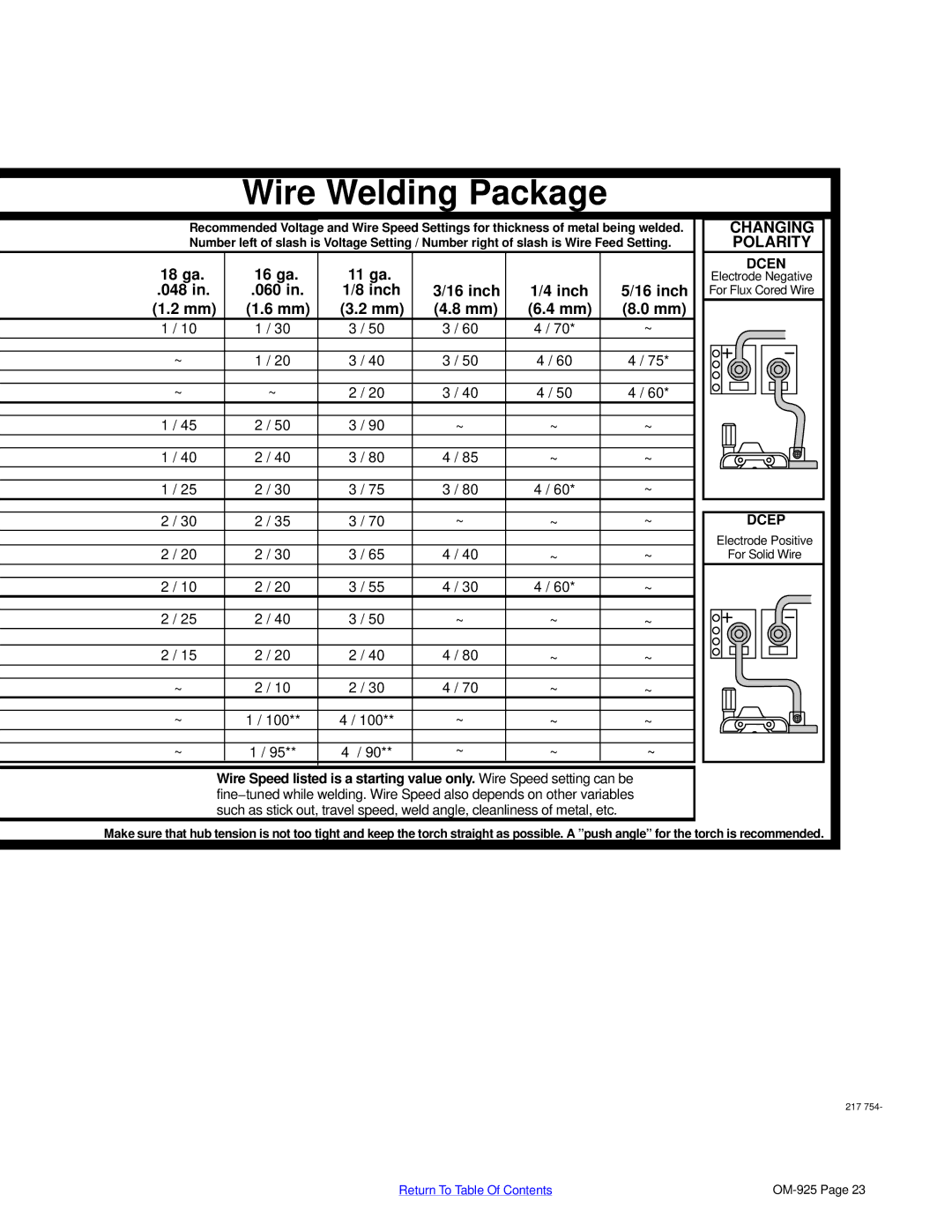
Wire Welding Package
Recommended Voltage and Wire Speed Settings for thickness of metal being welded.
Number left of slash is Voltage Setting / Number right of slash is Wire Feed Setting.
18 ga. | 16 ga. | 11 ga. |
|
|
|
.048 in. | .060 in. | 1/8 inch | 3/16 inch | 1/4 inch | 5/16 inch |
(1.2 mm) | (1.6 mm) | (3.2 mm) | (4.8 mm) | (6.4 mm) | (8.0 mm) |
1 / 10 | 1 / 30 | 3 / 50 | 3 / 60 | 4 / 70* | ~ |
|
|
|
|
|
|
~ | 1 / 20 | 3 / 40 | 3 / 50 | 4 / 60 | 4 / 75* |
|
|
|
|
|
|
~ | ~ | 2 / 20 | 3 / 40 | 4 / 50 | 4 / 60* |
|
|
|
|
|
|
1 / 45 | 2 / 50 | 3 / 90 | ~ | ~ | ~ |
|
|
|
|
|
|
1 / 40 | 2 / 40 | 3 / 80 | 4 / 85 | ~ | ~ |
|
|
|
|
|
|
1 / 25 | 2 / 30 | 3 / 75 | 3 / 80 | 4 / 60* | ~ |
|
|
|
|
|
|
2 / 30 | 2 / 35 | 3 / 70 | ~ | ~ | ~ |
|
|
|
|
|
|
2 / 20 | 2 / 30 | 3 / 65 | 4 / 40 | ~ | ~ |
|
|
|
|
|
|
2 / 10 | 2 / 20 | 3 / 55 | 4 / 30 | 4 / 60* | ~ |
|
|
|
|
|
|
2 / 25 | 2 / 40 | 3 / 50 | ~ | ~ | ~ |
|
|
|
|
|
|
2 / 15 | 2 / 20 | 2 / 40 | 4 / 80 | ~ | ~ |
|
|
|
|
|
|
~ | 2 / 10 | 2 / 30 | 4 / 70 | ~ | ~ |
|
|
|
|
|
|
~ | 1 / 100** | 4 / 100** | ~ | ~ | ~ |
|
|
|
|
|
|
~ | 1 / 95** | 4 / 90** | ~ | ~ | ~ |
Wire Speed listed is a starting value only. Wire Speed setting can be fine−tuned while welding. Wire Speed also depends on other variables such as stick out, travel speed, weld angle, cleanliness of metal, etc.
CHANGING |
POLARITY |
DCEN |
Electrode Negative |
For Flux Cored Wire |
DCEP |
Electrode Positive |
For Solid Wire |
Make sure that hub tension is not too tight and keep the torch straight as possible. A ”push angle” for the torch is recommended.
217 754-
Return To Table Of Contents |