13A-344-563 specifications
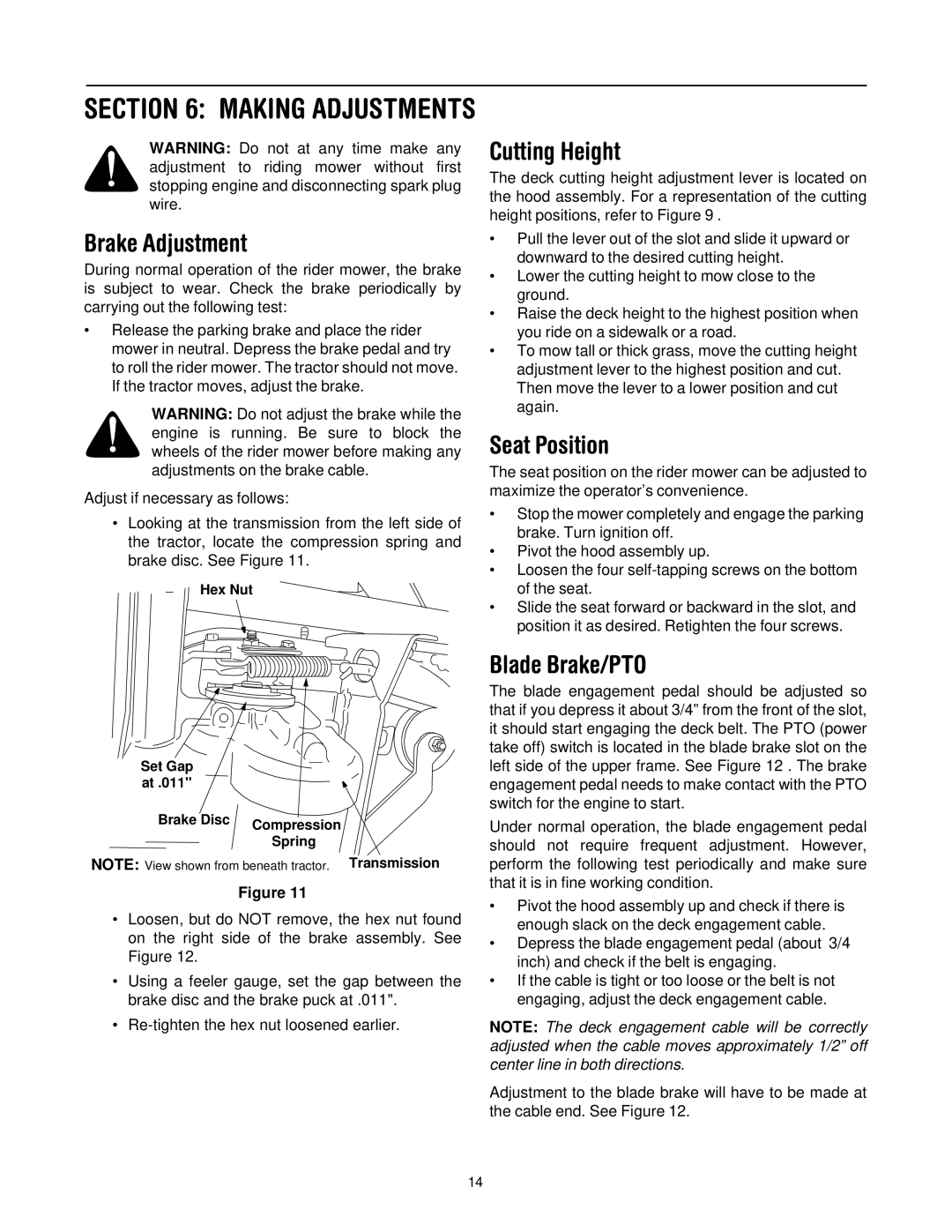
The Troy-Bilt 13A-344-563 is a robust and reliable tiller that caters to both gardening enthusiasts and professional landscapers alike. Known for its durability and efficiency, this tiller is designed to make the often labor-intensive process of soil cultivation easier and more effective.One of the standout features of the Troy-Bilt 13A-344-563 is its powerful engine. Equipped with a reliable 3.5 HP engine, this tiller is capable of tackling tough soil conditions with ease. The engine's performance ensures that gardeners can break up hard, compacted soil efficiently, allowing for better plant growth and a healthier garden.
The tiller is also designed with a large tilling width of up to 16 inches, enabling users to cover more ground in less time. This feature is particularly advantageous for those with larger gardens or landscaping projects. Alongside its width, the tiller has a tilling depth of up to 8 inches, making it suitable for a variety of soil types and gardening tasks.
The Troy-Bilt 13A-344-563 incorporates patented technologies that enhance its ease of use. One such feature is the adjustable tilling depth, which allows users to customize how deep they want to till based on the specific needs of their garden. Additionally, its rear-tine design helps to maintain stability and provides a smoother operation when maneuvering around different garden terrains.
Furthermore, the tiller boasts a user-friendly design with an ergonomic handle that reduces fatigue during prolonged use. The handles are adjustable, allowing users of various heights to find a comfortable position while operating the machine. This thoughtful design is geared towards maximizing efficiency without sacrificing user comfort.
Maintenance is also a breeze with the Troy-Bilt 13A-344-563. Its easy-access oil fill and dipstick make routine checks and changes hassle-free. Additionally, the robust construction ensures that the machine can withstand regular use over an extended lifespan.
In summary, the Troy-Bilt 13A-344-563 combines powerful performance, versatile features, and user-friendly design, making it a valuable addition to any gardener’s toolkit. Whether preparing soil for planting or cultivating existing beds, this tiller stands out for its ability to deliver reliable, effective results that promote healthy, vibrant gardens.

