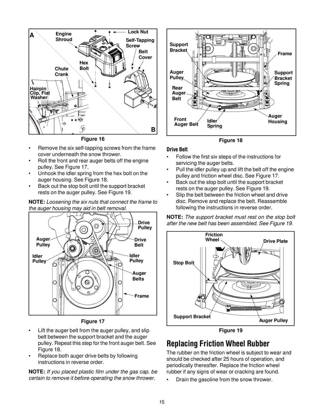
A | Engine | Lock Nut |
|
|
|
|
|
| |||
| Shroud | Support |
|
| |
|
| Screw |
|
| |
|
| Belt | Bracket |
| Frame |
|
|
|
| ||
|
| Cover |
|
| |
|
|
|
|
| |
|
| Hex |
|
|
|
| Chute | Bolt | Auger |
| Support |
| Crank |
|
| ||
|
| Pulley |
| Bracket | |
|
|
|
| ||
Hairpin |
|
| Rear |
| Spring |
|
|
|
| ||
Clip, Flat |
|
| Auger |
|
|
Washer |
|
| Belt |
|
|
|
|
| Front | Idler | Auger |
|
|
| Housing | ||
|
|
| Auger Belt | ||
|
| B | Spring |
| |
|
|
|
| ||
|
|
|
|
|
Figure 16 | Figure 18 | |
• Remove the six | Drive Belt | |
cover underneath the snow thrower. | • Follow the first six steps of the instructions for | |
• Roll the front and rear auger belts off the engine | ||
servicing the auger belts. | ||
pulley. See Figure 17. | ||
• Pull the idler pulley up and lift the belt off the engine | ||
• Unhook the idler spring from the hex bolt on the | ||
pulley and friction wheel disc. See Figure 17. | ||
auger housing. See Figure 18. | ||
• Back out the stop bolt until the support bracket | ||
• Back out the stop bolt until the support bracket | ||
rests on the auger pulley. See Figure 19. | ||
rests on the auger pulley. See Figure 19. | ||
• Slip the belt between the friction wheel and drive | ||
| ||
NOTE: Loosening the six nuts that connect the frame to | disc. Remove and replace the belt. Reassemble | |
the auger housing may aid in belt removal. | following the instructions in reverse order. |
| Drive | NOTE: The support bracket must rest on the stop bolt | |
| after the new belt has been assembled. See Figure 19. | ||
| Pulley |
|
|
Auger |
| Friction |
|
Drive | Wheel | Drive Plate | |
Pulley | Belt |
| |
|
| ||
Idler | Idler |
|
|
Pulley | Pulley | Stop Bolt |
|
|
|
| |
| Auger |
|
|
| Belts |
|
|
| Frame |
|
|
Figure 17 |
| Support Bracket | Auger Pulley |
|
| ||
•Lift the auger belt from the auger pulley, and slip belt between the support bracket and the auger pulley. Repeat this step for the front auger belt. See Figure 18.
•Replace both auger drive belts by following instructions in reverse order.
NOTE: If you placed plastic film under the gas cap, be certain to remove it before operating the snow thrower.
Figure 19
Replacing Friction Wheel Rubber
The rubber on the friction wheel is subject to wear and should be checked after 25 hours of operation, and periodically thereafter. Replace the friction wheel rubber if any signs of wear or cracking are found.
•Drain the gasoline from the snow thrower.
15