SECTION2: ASSEMBLY
WARNING: To prevent
personal injury or property damage,do not start the engine until all assemblysteps are complete andyou have read and understandthe safety and operating instructions in this manual.
INTRODUCTION
Carefully follow these assemblysteps to correctly prepareyour tiller for use. It is recommendedthatyou readthis Sectionin its entirety before beginning assembly.
NOTE: Various rifler models are presented in this Manual. Use only the information appropriate for your tiller model. Engine styles vary by model, Your engine may appear differently than those illustrated in this manual.
INSPECTUNIT
Inspect the unit and carton for damageim- mediatelyafter delivery.Contactthe carrier (trucking company) if you find or suspect damage. Inform them of the damageand request instructions for filing a claim. To protect your rights, put your claim in writ- ing and mail a copyto the carrier within 15 days after the unit has beendelivered.
TOOLS/ MATERIALSNEEDED
(2) 1/2"
(2) 9/16"
(1) 3/8"
(1)Largeadjustable wrench (Models 644A only)
(1) Scissors (to trim plastic ties)
(1) Ruler (for belt tension check)
(1)Block of wood (to support tiller when removing wheels)
(1)Tire pressure gauge (for models with pneumatic tires)
(1) Cleanoil funnel
(1)Motor oil. Referto the EngineOwner's Manualfor oil specificationsand quantity required.
* Adjustable wrenches may be used.
ASSEMBLYSTEPS
STEP 1: UNPACKING INSTRUCTIONS
NOTE:While unpacking, do not severely bend any control cables.
1.The tiller weighs approximately 133 Ibs. Do not attempt to remove it from the ship- ping platform until instructed to do so in these Assembly steps.
2.Removeany packagingmaterial from
the carton. Removeany staples from the bottom of the carton and removethe car- ton from the shipping platform.
3.Removeall unassembled parts andthe separatehardware bag from the carton. Checkthat you havethe items listed in the Loose Parts List (contactyour local dealer or the factory items are missing or dam- aged).
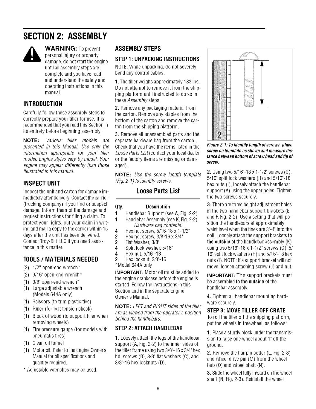
NOTE: Use the screw length template (Fig,
LooseParts List
Qty.Description
1HandlebarSupport (seeA, Fig.
1HandlebarAssembly(seeK,
4Hexhd. screw,
2Hexhd. screw,
2 FlatWasher,3/8"
4Split lock washer,5/16"
4Hex nut,
2HexIocknut,
IMPORTANT: Motor oil must beaddedto
the enginecrankcasebefore the engine is started. Followthe instructions inthis
Sectionand in the separateEngine Owner'sManual.
NOTE: LEFTand RIGHTsides of the tiller
are as viewed from the operator's position behind the handlebars.
STEP 2: ATTACH HANDLEBAR
1.Looselyattachthe legs of the handlebar support (A, Fig.
_iiii
Figure2-1: Toidentifylengthofscrews,place screwontemplateasshownandmeasuredis- tancebetweenbottomofscrewheadandtip of
screw.
2.Usingtwo
3.Therearethree height adjustment holes in the two handlebar support brackets (E and F,Fig.
the outsideofthe handlebarassembly (K) using two
IMPORTANT: The support bracketsmust beassembled to the outsideof the handlebarassembly.
4.Tightenall handlebarmounting hard- ware securely.
STEP 3: MOVE TILLER OFF CRATE To roll the tiller off the shipping platform, put the wheels in freewheel, as follows:
1.Placeasturdy block underthe transmis- sion to raise one wheel about 1" off the
ground.
2, Removethe hairpin cotter (L, Fig.
3.Slidethe wheelfully inward onthe wheel shaft (N, Fig.