| C |
P |
|
N | O |
|
Figure 2-4: Attach handlebars.
5.Move the handlebars up or down to align the threaded hole in the
6.Thread the height adjustment screw (F, Figure
7.To remove the tiller from its shipping platform, first carefully unwrap the wheel gear cable (with attached lever - see Figure
G
Figure 2-5: Carefully unwrap Wheel Gear Le- ver and move lever to DISENGAGE.
NOTE: The Wheel Gear Lever will be installed later in this procedure.
IMPORTANT: Use the DISENGAGE position only when the engine is not running. Before starting the engine, the Wheel Gear Lever must be placed in the ENGAGE position (see Section 3 for details).
STEP 3: ATTACH REVERSE CLUTCH CONTROL CABLE
1.Carefully unwrap the reverse clutch
control cable (H, Figure
Left Side | Reverse Clutch | |
Handlebar | ||
Control Knob | ||
|
Slot in Control Panel
![]() I
I
![]() H
H
Figure 2-6: Attach reverse clutch control as- sembly to slotted hole in handlebar panel.
2.Insert the cable into the slot in the con- trol panel and fit the threaded assembly into the hole in the slot (see Figure
3.Test the function of the reverse clutch control cable by pulling the knob out and releasing it. The knob should return to its neutral position against the tapered bush- ing. If it doesn’t, contact your local dealer or the factory for technical.
STEP 4: ATTACH FORWARD CLUTCH CONTROL CABLE
1.Remove any fasteners (rubber bands, tape, etc.) that may secure the Forward Clutch Control levers (J, Figure
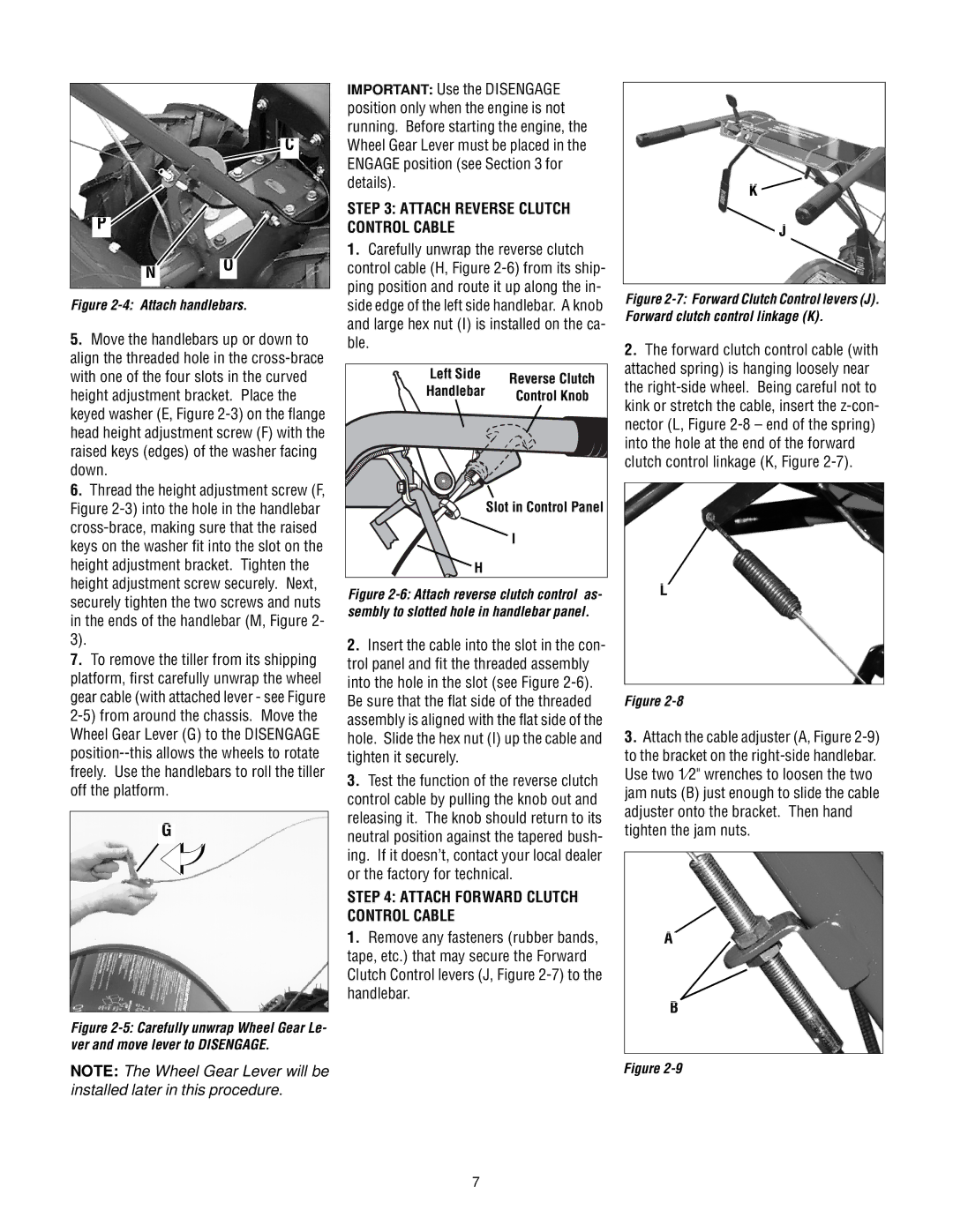
K ![]()
J
Figure 2-7: Forward Clutch Control levers (J). Forward clutch control linkage (K).
2.The forward clutch control cable (with attached spring) is hanging loosely near the
L
Figure
3.Attach the cable adjuster (A, Figure 2-9)
to the bracket on the
A![]()
B
Figure
7