Troy-Bilt 769-00425A manual Operating Instructions, Assembling The Coupler, Removing the Add-Ons

Models: 769-00425A

1 48
Download 48 pages 60.42 Kb
Page 7
Image 7
OPERATING INSTRUCTIONS

OPERATING INSTRUCTIONS

ASSEMBLING THE COUPLER

The following Troy-Bilt Add-Ons are also available for your unit: Blower/Vacuum . . . . . . . . . . . . . . . . . . . . . . . . . . . TBBV Cultivator . . . . . . . . . . . . . . . . . . . . . . . . . . . . . . . . TBGC Hedge Trimmer . . . . . . . . . . . . . . . . . . . . . . . . . . . TBHS Edger . . . . . . . . . . . . . . . . . . . . . . . . . . . . . . . . . . . TBLE Snow Thrower . . . . . . . . . . . . . . . . . . . . . . . . . . . . TBST Turbo Blower . . . . . . . . . . . . . . . . . . . . . . . . . . . . . TBTB Tree Pruner . . . . . . . . . . . . . . . . . . . . . . . . . . . . . . TBTP

Removing the Add-Ons

WARNING: Read and understand operator’s manual for unit to be used with this add-on prior to operation.

1.Turn the knob counterclockwise to loosen (Fig. 1).

2.Press and hold the release button (Fig. 1).

3.While firmly holding the upper shaft housing, pull the add-on straight out of the coupler (Fig.2).

Installing the Add-Ons

WARNING: To avoid serious personal injury and damage to the unit, shut unit off before removing or installing add-ons.

NOTE: To make installing or removing the add-on easier, place the unit on the ground or on a work bench.

1.Remove the hanger from the top of the lower shaft housing.

2.Turn the knob counterclockwise to loosen (Fig. 1).

3.While firmly holding the add-on, push it straight into the coupler (Fig. 2).

NOTE: Aligning the release button with the guide recess will help installation (Fig. 1).
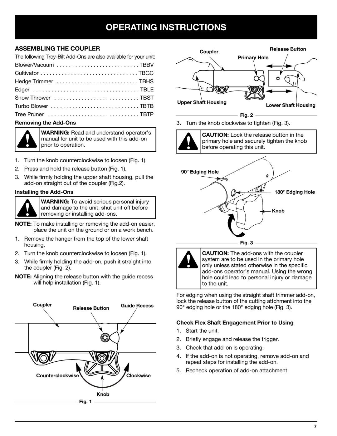
Coupler

Release Button

Guide Recess


CounterclockwiseClockwise

Knob

Fig. 1

Coupler

Release Button

Primary Hole


Upper Shaft Housing

Lower Shaft Housing

Fig. 2

3. Turn the knob clockwise to tighten (Fig. 3).

CAUTION: Lock the release button in the primary hole and securely tighten the knob before operating this unit.

90° Edging Hole

180° Edging Hole

ASSEMBLING THE COUPLER Knob

Fig. 3

CAUTION: The add-ons with the coupler system are to be used in the primary hole only unless stated otherwise in the specific add-ons operator’s manual. Using the wrong hole could lead to personal injury or damage to the unit.

For edging when using the straight shaft trimmer add-on, lock the release button of the cutting attchment into the 90° edging hole or the 180° edging hole (Fig. 3).

Check Flex Shaft Engagement Prior to Using

1.Start the unit.

2.Briefly engage and release the trigger.

3.Check that add-on is operating.

4.If the add-on is not operating, remove add-on and repeat steps for installing the add-on.

5.Recheck operation of add-on attachment.

7

Page 7
Image 7
Troy-Bilt 769-00425A manual Operating Instructions, Assembling The Coupler, Removing the Add-Ons, Installing the Add-Ons